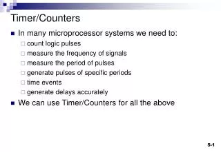
Timer/Counters
Timer/Counters. In many microprocessor systems we need to: count logic pulses measure the frequency of signals measure the period of pulses generate pulses of specific periods time events generate delays accurately We can use Timer/Counters for all the above. Binary Counters.

Timer/Counters
E N D
Presentation Transcript
Timer/Counters • In many microprocessor systems we need to: • count logic pulses • measure the frequency of signals • measure the period of pulses • generate pulses of specific periods • time events • generate delays accurately • We can use Timer/Counters for all the above
Binary Counters Overflow bit This bit is set to one when the binary counter rolls over from all 1's back to 0's (Can be reset to zero by software) Clock signal n-bit Counter Counter increments by one for every clock pulse Counter can be pre-loaded with a starting value
Timer/Counters • The clock source can be • a fixed known frequency • usually the cpu clock or some fraction of it • An external signal – connected to an external pin. This allows the counting of pulses • Some systems connect the overflow bit via a flip-flop to an output pin which is toggled every time an overflow occurs. Used for waveform generation (PWM). • The overflow flag can be polled or used to generate an interrupt to the CPU.
PIC 18F452 Timer0 – 16 bit mode Note: Upon RESET, Timer0 is enabled in 8-bit mode with clock input from T0CKI max. prescale.
To generate a fixed delay • Configure T0CON • timer mode • 8 or 16 bit • prescaler • Load TMR0 with vale to give correct time delay • NOTE: - High byte first then low byte • Clear TMR0IF to zero (Bit 2 of INTCON register) • Start timer by setting TMR0ON (bit 7 of T0CON) • Poll TMR0IF – wait until bit is set. Alternatively use interrupts (a future lecture topic).
To measure a time period • Configure T0CON • timer mode • 8 or 16 bit • prescaler • Clear TMR0 - High byte first then low byte • Clear TMR0IF to zero (may not be required) • When the event starts • Start timer by setting TMR0ON (bit 7 of T0CON) • When the event is over • Stop the timer by clearing TMR0ON • Read the value from TMR0 (Read low byte first!)
A 100ms delay • CPU Clock frequency fosc= 4MHz , Timer input clock frequency = 4MHz /4 = 1MHz so period = 1us • Max count for 16-bit TMR0 = 2^16 = 65536 counts • So max timer period = 65536 x 1us =65.536ms • Need to use prescaler Prescaler Resolution Max period 2 2us 65536x2us = 131.072ms 4 4us 262.144ms etc. 256 256uS 16.777216 seconds
Cont. • So need prescaler set to 2. • Timer input period = 2x1us = 2us • Number of counts = time period/timer input period = 100ms/2us = 100000/2 = 50000 • Value to load into timer = 65536 – 50000 = 15536 • movlw high(15536) • movwf TMR0H • movwf low(15536) • movwf TMR0L • bcf INTCON,TMR0IF
Measure a time period ;Initialise timer 0 movlw 0x03 ;Prescaler = 16, so increment timer every 16us movwf T0CON ; with 4MHz Osc ;reset timer registers to zero clrf TMR0H ;notice order:high then low byte clrf TMR0L ; The event start is detected so start timer bsf T0CON,TMR0ON ; Wait for the event to end ; The event is over so stop timer bcf T0CON,TMR0ON ;Calc time taken movff TMR0L,TIML ;Note order of reading - Low then high byte movff TMR0H,TIMH