Download
1 / 28
280 likes | 412 Views
Strategies for Monitoring a Large Volume Commercial Injection – a Hypothesis and a Test Program. Susan Hovorka, Ram ón Treviño, Tip Meckel Gulf Coast Carbon Center, Bureau of Economic Geology, Jackson School of Geosciences, The University of Texas at Austin.

E N D
Strategies for Monitoring a Large Volume Commercial Injection – a Hypothesis and a Test Program Susan Hovorka, Ramón Treviño, Tip Meckel Gulf Coast Carbon Center, Bureau of Economic Geology, Jackson School of Geosciences, The University of Texas at Austin Presented to 7th Annual Conference of Carbon Capture and Sequestration sponsored by NETL, May -5-8, 2008 Pittsburg, PA
Gulf Coast Carbon Center (GCCC) GCCC Research Team: Susan Hovorka, Tip Meckel, J. P. Nicot, Ramon Trevino, Jeff Paine, Becky Smyth; Post-doc and students Associate DirectorIan Duncan Director Scott Tinker Newest member: Sempra
GCCC Field Tests for Monitoring and Verification Technologies - DOE-NETL and Industry Hosts SECARB Phase II&II Denbury Cranfield Frio Test Site Texas American Resources SACROC Southwest Partnership KinderMorgan NM Tech
Monitoring Schemes: Monitoring in Mature Commercial Context • Benson study showed cost of a monitoring scheme, basic or enhanced, is a small fraction of the cost of the whole project. • Should a large injection then have a large monitoring program? ?
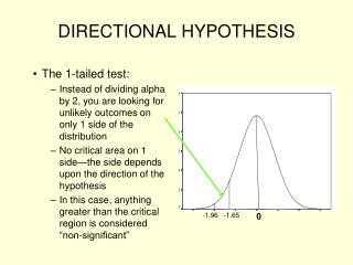
A balanced and phased approach to permitting and monitoring Balanced Phased Adequate rigor to assure that early programs do not fail Not too restrictive: encourage early entry into CCS – gain experience; Learn by doing Early (now) Mature (As defined by time? Or by injection volume?) Adequately rigorous to assure performance and public acceptance Standardized, parsimonious
Current Monitoring Approaches Are Not Mature West Pearl -Queen Weyburn Cranfield SACROC White papers InSalah Class II Frio Otway Class I Sliepner
Need for Parsimonious Monitoring Program in a Mature Industry • Standardized, dependable, durable instrumentation • Reportable measurements • Possibility of above-background detection: • Need for a follow-up testing program • Hierarchical approach : Not within acceptable limits: Parameter A Not within acceptable limits: test Parameter B Stop & mitigate Within acceptable limits: continue Within acceptable limits: continue
Two Areas of Concern in Area of Review Footprint of area of elevated pressure 2 Injection well 1 Footprint of area over CO2 Most workers in CCS are most concerned about area (1). Most UIC is concerned about area 1 +2 Plume of injected CO2
Risk is different in different parts of the AOR, and changes with time Footprint of area of elevated pressure Leakage risk is for brine into USDW or to surface water Injection well Footprint of area over CO2 Leakage risk is for CO2 into the atmosphere, also possibility for damage to biosphere, to USDW or surface water
The relative size of both parts of the area of review is sensitive to geologic characterization Case A has a pressure seal essentially no fluid flow under possible pressure contrasts. The area of pressure elevation is large relative to area of CO2 foot print 2 1 A Case B has a capillary entry seal vertical hydraulic conductivity contrast allows brine movement however CO2 cannot cross the seal. The area of pressure elevation is smaller relative to area of CO2 foot print. 2 1 B
New proposal - monitoring box Parsimonious Monitoring Hypothesis Complex! • Atmosphere • Ultimate receptor but dynamic • Biosphere • Assurance of no damage but dynamic • Soil and Vadose Zone • Integrator but dynamic • Aquifer and USDW • Integrator, slightly isolated from ecological effects • Above injection monitoring zone • First indicator, monitor small signals, stable. • In injection zone - plume • Oil-field type technologies. Will not identify small leaks • In injection zone - outside plume • Assure lateral migration of CO2 and brine is acceptable Atmosphere Biosphere Vadose zone & soil Aquifer and USDW Seal Complex! Monitoring Zone Seal CO2 plume
Large volume injection plan Array of injection wells with horizontal completions Upper Seal – Salado-Tansill Monitoring zone - Yates Lower Seal – Seven Rivers Delaware Mountain Group Thick section of fine sandstone and organic-rich siltstones
Above zone array Monitoring wells of the ‘box” sides Large volume monitoring plan – the box Dip Major fracture orientation Horizontal injectors and CO2 plumes Area of elevated pressure
Test Plan • Correctness of assumptions • Viablity in the field • Test site at Cranfield
Saturation at injectors Monitoring Plan Saturation logging program at injectors Excellent baseline surveys – air, soil, water, 3-D seismic Pressure at injector Injection Far-field pressure 40 0 years
Saturation at injectors Far-field pressure much Higher than expected Asymmetrical pressure plume Low saturation= Poor sweep efficiency = large CO2 plume Pressure much Lower than expected= a leak? Monitoring Plan – finds unacceptable response Reservoir not arealy Extensive? Saturation logging program at injectors Excellent baseline surveys – air, soil, water, 3-D seismic Pressure at injector Injection Far-field pressure 40 0 years
Cranfield as Case Study • Reservoir produced to depletion1945-1965, all wells plugged and abandoned. • Water invasion, pressure recovery 40 years • Brine is mobile phase, pressure hydrostatic • Dense data, wells reentered as access points. • Down-dip injection – pressure support to prevent oil escape downdip. • Produced by gas lift after CO2 breakthrough • No water injection
Saline aquifer within Cranfield unit Phase II study area Dedicated observation well pattern of logging in producers Phase III study area Two observation wells, monitoring and limited logging in producers SECARB (early) Phase II-III Field test Cranfield Unit setting Denbury early injectors Gas cap Sonat CO2 pipeline Oil ring Cranfield unit boundary Denbury later Injectors shown schematically
Phase II Research Focuses (1) Sweep efficiency – how effectively are pore volumes contacted by CO2? • Important in recovery efficiency in EOR • For storage – what is capacity of subsurface? Prediction of plume size (2) Injection volume is sum of fluid displacement, dilatancy, dissolution, and rock+fluid compression • Bottom hole pressure mapping to estimate fluid displacement (3) Effectiveness of Mississippi well completions regulations in retaining CO2 in GHG context • Above zone monitoring
Phase III Research Focuses (1) Sweep efficiency – how effectively are pore volumes contacted by CO2? • High injection rates in brine • How much CO2 is dissolved? Compare brine to EOR • Cross-well program to assess sweep at high injection rates (2) Injection volume is sum of fluid displacement, dilatancy, dissolution, and rock+fluid compression • Tilt to start to understand magnitude of dilatancy • Bottom hole pressure mapping to estimate fluid displacement • Real-time cross-well program to map plume –pressure relationships (3) Surface test plan – assess the effectiveness of surface monitoring in an area of deep water table
Two areas need monitoring: buoyant CO2 and elevated pressure in brine In EOR CO2 injection is approximately balanced by oil, CO2, and brine production no pressure plume beyond the CO2 injection area CO2 injection (no production) pressure plume extends beyond the CO2 injection area Elevated pressure CO2 plume Elevated pressure
16" casing set @ 222' 10-3/4" casing set @ 1,825' Test adequacy of Mississippi well completions for CO2 sequestration MonitoringZone 13-Chrome Isolation packer w/ feed through 13-Chrome Selective seat nipple Pressure transducer Side Pocket Mandrel w/dummy gas valve 1/4" tubing installed between packers to Provide a conduit between isolation packers Confining system CO2 Injection Zone 13-Chrome Production packer w/ feed thrus Tuscaloosa perforation Pressure transducer Side Pocket Mandrel w/dummy gas valve 7" casing set @ 10,305'
Phase III Early Test: Brine interval Phase II Area The area selected for the Phase III Early Test is immediately north of the SECARB Phase II “Stacked Storage” study underway, within unitized field.
Inj + Mon Inj+ Mon Inj+ Mon Inj Inj + Mon Moni toring Oil Prod Proposed Phase III Early study area Phase II Study area Cranfield Program Overview A’ Denbury Cranfield unit A Documented seal Residual Gas 10,000 ft Residual Oil A’ Tuscaloosa Formation Brine A
Parameter A Not within acceptable limits: Parameter B Stop & mitigate Not within acceptable limits test Within acceptable limits: continue Hypothesis: Parsimonious Monitoring Program in a Mature Industry • Standardized, dependable, durable instrumentation, reportable measurements • Frequent pressure measurements above-zone and in-zone – documents conformance • Episodic saturation logging (at injectors?) syn-and post-injection documents sweep. • Trigger points: • an unexpected measurement initiates a pre-planned research type monitoring program to assess origin of response.
PHASE II OBSERVATION WELL LOCATION Monitor Sand Marine Shale Seal 375’ Injection Sand 3 MMCFD Injection rates Phase II : ½ Million Tons/yr Phase III : 1-1.5 Mt/yr
Returned into the earth where it came from Geologic Sequestrationof Carbon – Put it back Carbon extracted from coal or other fossil fuel… www.gulfcoastcarbon.org