Ch. 8 VLANs Virtual LANs
730 likes | 1.05k Views
Rick Graziani graziani@cabrillo.edu. 2. Switch Technologies in Cisco 3. Port SecuritySpanning Tree ProtocolVLANsVLAN Trunking Protocol (VTP) and Inter-VLAN Routing. Rick Graziani graziani@cabrillo.edu. 3. Overview. Define VLANs List the benefits of VLANs Explain how VLANs are used to create b

Ch. 8 VLANs Virtual LANs
E N D
Presentation Transcript
1. Ch. 8 � VLANs (Virtual LANs) CCNA 3 version 3.0
Rick Graziani
Cabrillo College
Modified by Valerie Fronczak
Hocking College
2. Rick Graziani graziani@cabrillo.edu 2 Switch Technologies in Cisco 3 Port Security
Spanning Tree Protocol
VLANs
VLAN Trunking Protocol (VTP) and Inter-VLAN Routing
3. Rick Graziani graziani@cabrillo.edu 3 Overview Define VLANs
List the benefits of VLANs
Explain how VLANs are used to create broadcast domains
Explain how routers are used for communication between VLANs
List the common VLAN types
Define ISL and 802.1Q
Explain the concept of geographic VLANs
Configure static VLANs on 29xx series Catalyst switches
Verify and save VLAN configurations
Delete VLANs from a switch configuration
4. Rick Graziani graziani@cabrillo.edu 4 Background In the mid 1990�s, switches became faster and cheaper
Network designers began to implement �flat� networks, that is, networks that used switches to make one big, happy network
This was also based on the �routers bad, switches good� mentality
Could switch product marketers have had something to do with this? �����.Hhmm?
5. Rick Graziani graziani@cabrillo.edu 5 If one switch is good�
6. Rick Graziani graziani@cabrillo.edu 6 More is better
7. Rick Graziani graziani@cabrillo.edu 7 And More..
8. Rick Graziani graziani@cabrillo.edu 8 And More !
9. Rick Graziani graziani@cabrillo.edu 9 What is the problem with a flat topology?
10. Rick Graziani graziani@cabrillo.edu 10 Broadcast Domain
11. Rick Graziani graziani@cabrillo.edu 11 Broadcast Domain
12. Rick Graziani graziani@cabrillo.edu 12 Broadcast Domain
13. Rick Graziani graziani@cabrillo.edu 13 Consider this situation:
14. Rick Graziani graziani@cabrillo.edu 14 Consider this situation:
15. Rick Graziani graziani@cabrillo.edu 15 Virtual LANs
16. Rick Graziani graziani@cabrillo.edu 16 Virtual LANs VLANs are implemented through software on a switch
By creating VLANs, the devices on VLAN A are completely isolated from the devices on VLAN B, even though they are connected to the same switch
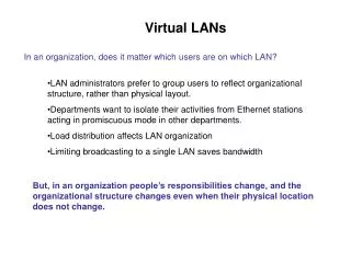
17. Rick Graziani graziani@cabrillo.edu 17 VLAN Introduction VLANs provide segmentation based on broadcast domains.
VLANs logically segment switched networks based on the functions, project teams, or applications of the organization regardless of the physical location or connections to the network.
All workstations and servers used by a particular workgroup share the same VLAN, regardless of the physical connection or location.
VLANs facilitate easier administration of moves, adds, and changes in members of these group
18. Rick Graziani graziani@cabrillo.edu 18 VLAN introduction VLANs are created to provide segmentation services traditionally provided by physical routers in LAN configurations.
VLANs address scalability, security, and network management. Routers in VLAN topologies provide broadcast filtering, security, and traffic flow management.
Switches may not bridge any traffic between VLANs, as this would violate the integrity of the VLAN broadcast domain.
Traffic should only be routed between VLANs.
19. Rick Graziani graziani@cabrillo.edu 19 VLANs By creating three VLANs on this switch, this switch has essentially become three separate switches
The green, blue, and yellow switch ports are isolated from each other because the switch maintains a separate bridging table for each VLAN
20. Rick Graziani graziani@cabrillo.edu 20 VLAN-Capable Switches The switch maintains a separate bridging table for each VLAN.
If the frame comes in on a port in VLAN 1, the switch searches the bridging table for VLAN 1.
When the frame is received, the switch adds the source address to the bridging table if it is currently unknown.
The destination is checked so a forwarding decision can be made.
For learning and forwarding, the search is made against the address table for that VLAN only
21. Rick Graziani graziani@cabrillo.edu 21
22. Rick Graziani graziani@cabrillo.edu 22
23. Rick Graziani graziani@cabrillo.edu 23
24. Rick Graziani graziani@cabrillo.edu 24
25. Rick Graziani graziani@cabrillo.edu 25 Inter-VLAN Communication If you do want communication between VLANs you need a router
Routers provide communication between VLANs
This means that each VLAN must be a separate network or subnet, since routers route between different networks or subnet
26. Rick Graziani graziani@cabrillo.edu 26 VLANs, Subnets, and Broadcast Domains A VLAN = a subnet = a broadcast domain
The default configuration of a switch assigns all of the switch ports to VLAN 1; the switch consists of one broadcast domain; all devices connected to the switch see all broadcasts
If a switch has two VLANs then the devices in one VLAN are all in one subnet and the devices on the other VLAN are in another subnet; there are now two broadcast domains on the switch. The devices connected to the switch ports assigned to VLAN 1 only see the broadcasts from the other devices on VLAN 1. VLAN 2 devices only see broadcasts from the other VLAN 2 member devices
Four VLANs = four subnets = four broadcast domains
27. Rick Graziani graziani@cabrillo.edu 27 VLAN operation Important notes on VLANs:
VLANs are assigned on the switch port. There is no �VLAN� assignment done on the host (usually).
In order for a host to be a part of that VLAN, it must be assigned an IP address that belongs to the proper subnet.
Remember: VLAN = Subnet
28. Rick Graziani graziani@cabrillo.edu 28 Broadcast domains with VLANs and routers A VLAN is a broadcast domain created by one or more switches.
The network design above creates three separate broadcast domains.
29. Rick Graziani graziani@cabrillo.edu 29 Broadcast domains with VLANs and routers 1) No VLANs, or in other words, One VLAN. Single IP network.
2) With or without VLANs. However this can be and example of no VLANS. In both examples, each group (switch) is on a different IP network.
3) Using VLANs. Switch is configured with the ports on the appropriate VLAN.
What are the broadcast domains in each?
30. Rick Graziani graziani@cabrillo.edu 30 VLAN operation Each switch port can be assigned to a different VLAN.
Ports assigned to the same VLAN share broadcasts.
Ports that do not belong to that VLAN do not share these broadcasts.
31. Rick Graziani graziani@cabrillo.edu 31 VLAN operation Static membership VLANs are called port-based and port-centric membership VLANs.
As a device enters the network, it automatically assumes the VLAN membership of the port to which it is attached.
�The default VLAN for every port in the switch is the management VLAN. The management VLAN is always VLAN 1 and may not be deleted.�
This statement does not give the whole story. The management VLAN can be set to another VLAN besides VLAN 1. There are reasons for doing this.
All other ports on the switch may be reassigned to alternate VLANs.
32. Rick Graziani graziani@cabrillo.edu 32 VLAN operation Dynamic membership VLANs are created through network management software. (Not as common as static VLANs)
CiscoWorks 2000 or CiscoWorks for Switched Internetworks is used to create Dynamic VLANs.
Dynamic VLANs allow for membership based on the MAC address, logical (layer 3 ) address, or protocol type of the device connected to the switch port.
As a device enters the network, the switch that it is connected to queries a database on the VLAN Configuration Server for VLAN membership.
33. Rick Graziani graziani@cabrillo.edu 33 Benefits of VLANs The key benefit of VLANs is that they permit the network administrator to organize the LAN logically instead of physically.
Note: Can be done without VLANs, but VLANs limit the broadcast domains
This means that an administrator is able to do all of the following:
Easily move workstations on the LAN.
Easily add workstations to the LAN.
Easily change the LAN configuration.
Easily control network traffic.
Improve security.
34. Rick Graziani graziani@cabrillo.edu 34 VLAN Types
35. Rick Graziani graziani@cabrillo.edu 35 Static VLANs Static (port-based, port centric) VLANs are ports on a switch that are manually assigned to a VLAN
This can be accomplished with a VLAN management application or configured directly into the switch through the CLI
These ports maintain their assigned VLAN configuration until they are changed manually
This type of VLAN works well in networks with specific requirements:
All moves are controlled and managed.
Workstations, departments, and network resources are seldom moved
There is robust VLAN management software to configure the ports.
The additional overhead required to maintain end-station MAC addresses and custom filtering tables is not acceptable
36. Rick Graziani graziani@cabrillo.edu 36 MAC address Based VLANs Rarely implemented.
37. Rick Graziani graziani@cabrillo.edu 37 VLAN Tagging Each frame entering a switch is �tagged� with its VLAN ID
There a several methods of tagging
Before a standard was developed, Cisco invented their own method of tagging called ISL (Inter-Switch Link). This method is proprietary to Cisco switches
The networking community later developed a tagging standard: 802.1Q
Tags are ONLY used within the switching infrastructure, that is, inside the switch or between switches.
Tags are removed (stripped) from any frames leaving a switch port to any device other than a switch
This is because only VLAN capable switches understand a tagged frame; to non-switch devices these frame would as �bad� or corrupted frames
38. Rick Graziani graziani@cabrillo.edu 38 VLAN Tags Multiple VLAN-capable switches can be connected together to appear as one big switch
The switches connect through a a trunk link
A trunk link is simply a link that transports VLAN tagged frames
39. Rick Graziani graziani@cabrillo.edu 39 VLAN Tagging VLAN Tagging is used when a link needs to carry traffic for more than one VLAN.
Trunk link: As packets are received by the switch from any attached end-station device, a unique packet identifier is added within each header.
This header information designates the VLAN membership of each packet.
The packet is then forwarded to the appropriate switches or routers based on the VLAN identifier and MAC address.
Upon reaching the destination node (Switch) the VLAN ID is removed from the packet by the adjacent switch and forwarded to the attached device.
Packet tagging provides a mechanism for controlling the flow of broadcasts and applications while not interfering with the network and applications.
This is known as a trunk link or VLAN trunking.
40. Rick Graziani graziani@cabrillo.edu 40 VLAN Tagging There are two major methods of frame tagging, Cisco proprietary Inter-Switch Link (ISL) and IEEE 802.1Q.
ISL used to be the most common, but is now being replaced by 802.1Q frame tagging.
Cisco recommends using 802.1Q.
VLAN Tagging and Trunking will be discussed in the next chapter.
41. Rick Graziani graziani@cabrillo.edu 41 Cisco Switches and Tagging Cisco 1900 switches can only implement ISL tagging
Cisco 2950 switches can only implement IEEE 802.1Q
Cisco 3550 switches can be set to implement ISL or 802.1Q tagging
Tagging between different vendors� switches doesn�t always work (what a surprise!)
42. Two VLAN Types End-to-End or Campus Wide
Geographic VLANs
43. Rick Graziani graziani@cabrillo.edu 43 End-to-End or Campus-wide VLANs
44. Rick Graziani graziani@cabrillo.edu 44 Geographic or Local VLANs
45. Rick Graziani graziani@cabrillo.edu 45 End-to-End or Campus-wide VLANs End-to-End or Campus-wide VLANs
Same VLAN/Subnet no matter what the location is on the network
Trunking at the Core
Usually not recommended by Cisco or other Vendors
Adds complexity to network administration
Does not resolve Layer 2 Spanning Tree issues
Use to be recommended with routing at the Core was considered to slow.
46. Rick Graziani graziani@cabrillo.edu 46 End-to-End or Campus-wide VLANs The core layer router is being used to route between subnets (VLANs).
The network is engineered, based on traffic flow patterns, to have 80 percent of the traffic contained within a VLAN.
The remaining 20 percent crosses the router to the enterprise servers and to the Internet and WAN.
Note: This is known as the 80/20 rule. With today�s traffic patterns, this rule is becoming obsolete.
47. Rick Graziani graziani@cabrillo.edu 47 Geographic or Local VLANs Geographic or Local VLANs
More common
Routing at the core
Different VLAN/Subnet depending upon location
48. Rick Graziani graziani@cabrillo.edu 48 Geographic or Local VLANs As many corporate networks have moved to centralize their resources, end-to-end VLANs have become more difficult to maintain.
Users are required to use many different resources, many of which are no longer in their VLAN.
Because of this shift in placement and usage of resources, VLANs are now more frequently being created around geographic boundaries rather than commonality boundaries.
49. Rick Graziani graziani@cabrillo.edu 49 Geographic or Local VLANs This geographic location can be as large as an entire building or as small as a single switch inside a wiring closet.
In a VLAN structure, it is typical to find the new 20/80 rule in effect. 80 percent of the traffic is remote to the user and 20 percent of the traffic is local to the user.
Although this topology means that the user must cross a Layer 3 device in order to reach 80 percent of the resources, this design allows the network to provide for a deterministic, consistent method of accessing resources.
50. Configuring VLANs on Cisco Switches Catalyst 2950 and 3550 switch configuration
51. Rick Graziani graziani@cabrillo.edu 51 Configuring static VLANs The following guidelines must be followed when configuring VLANs on Cisco 29xx switches:
The maximum number of VLANs is switch dependent.
29xx switches commonly allow 4,095 VLANs
VLAN 1 is one of the factory-default VLANs.
VLAN 1 is the default Ethernet VLAN.
Cisco Discovery Protocol (CDP) and VLAN Trunking Protocol (VTP) advertisements are sent on VLAN 1.
The Catalyst 29xx IP address is in the VLAN 1 broadcast domain by default.
�The switch must be in VTP server mode to create, add, or delete VLANs.� (This is not true. Switch could be in VTP Transparent mode. VTP will be discussed in a moment.)
52. Rick Graziani graziani@cabrillo.edu 52 Creating VLANs Assigning access ports (non-trunk ports) to a specific VLAN
Switch(config)#interface fastethernet 0/9
Switch(config-if)#switchport access vlan vlan_number
Create the VLAN: (This step is not required and will be discussed later.)
Switch#vlan database
Switch(vlan)#vlan vlan_number
Switch(vlan)#exit
53. Rick Graziani graziani@cabrillo.edu 53 VLAN Notes A created VLAN remains unused until it is mapped to switch ports. That is, if you create a VLAN but don�t assign any ports to the VLAN, then the VLAN is not being used in any way
All Ethernet ports are assigned to VLAN 1 by default.
54. Rick Graziani graziani@cabrillo.edu 54 Creating VLANs Assign ports to the VLAN
Switch(config)#interface fastethernet 0/9
Switch(config-if)#switchport access vlan 10
access � Denotes this port as an access port and not a trunk link (later)
55. Rick Graziani graziani@cabrillo.edu 55 Creating VLANs
56. Rick Graziani graziani@cabrillo.edu 56 Configuring Ranges of VLANs SydneySwitch(config)#interface fastethernet 0/5
SydneySwitch(config-if)#switchport access vlan 2
SydneySwitch(config-if)#exit
SydneySwitch(config)#interface fastethernet 0/6
SydneySwitch(config-if)#switchport access vlan 2
SydneySwitch(config-if)#exit
SydneySwitch(config)#interface fastethernet 0/7
SydneySwitch(config-if)#switchport access vlan 2
57. Rick Graziani graziani@cabrillo.edu 57 Configuring Ranges of VLANs SydneySwitch(config)#interface range f 0/8 , f 0/12
SydneySwitch(config-if)#switchport access vlan 3
SydneySwitch(config-if)#exit
This command does not work on all 2900 switches, such as the 2900 Series XL. It does work on the 2950.
58. Rick Graziani graziani@cabrillo.edu 58 Configuring Ranges of VLANs SydneySwitch(config)#interface range fastethernet 0/8 - 12
SydneySwitch(config-if)#switchport access vlan 3
SydneySwitch(config-if)#exit
This command works on the Catalyst 2960
59. Rick Graziani graziani@cabrillo.edu 59 Creating VLANs SydneySwitch(config)#interface fastethernet 0/1
SydneySwitch(config-if)#switchport mode access
SydneySwitch(config-if)#exit
Note: The switchport mode access command should be configured on all ports that the network administrator does not want to become a trunk port.
This will be discussed in more in the next chapter, section on DTP.
60. Rick Graziani graziani@cabrillo.edu 60 Creating VLANs By default, all ports are configured as switchport mode dynamic desirable, which means that if the port is connected to another switch with an port configured with the same default mode (or desirable or auto), this link will become a trunking link.
When the switchport access vlan command is used, the switchport mode access command is not necessary since the switchport access vlan command configures the interface as an �access� port (non-trunk port).
This will be discussed in more in the next chapter, section on DTP.
61. Rick Graziani graziani@cabrillo.edu 61 Verifying VLANs � show vlan
62. Rick Graziani graziani@cabrillo.edu 62 Verifying VLANs � show vlan brief
63. Rick Graziani graziani@cabrillo.edu 63 vlan database commands Optional Command to add, delete, or modify VLANs.
VLAN names, numbers, and VTP (VLAN Trunking Protocol) information can be entered which �may� affect other switches besides this one. (Discussed later).
This does not assign any VLANs to an interface.
Switch#vlan database
Switch(vlan)#?
VLAN database editing buffer manipulation commands:
abort Exit mode without applying the changes
apply Apply current changes and bump revision number
exit Apply changes, bump revision number, and exit mode
no Negate a command or set its defaults
reset Abandon current changes and reread current database
show Show database information
vlan Add, delete, or modify values associated with a single VLAN
vtp Perform VTP administrative functions.
64. Rick Graziani graziani@cabrillo.edu 64 Deleting VLANs To remove a VLAN from an interface, simply use the no form of the command
Switch(config-if)#no switchport access vlan vlan_number
65. Troubleshooting VLANs
66. Rick Graziani graziani@cabrillo.edu 66 Broadcast Storms in Switched Networks Spanning Tree Protocol is used in switched networks to prevent loops and and eliminate or reduce the possibility of broadcast storms
Problems can still occur in large and complex networks
Minimize spanning-tree problems by actively developing a baseline study of the network
The root bridge is the central point of a spanning-tree configuration that controls how the protocol operates
Identifying the root bridge in the extended router and switch network is necessary for effective troubleshooting
The show spanning tree command on both routers and switches can display root-bridge and timer information
If the network encounters a period of instability, it helps to minimize the STP processes occurring between devices; in other words; decrease the BPDU traffic by adjusting the timers on the root bridge. This timer information is then propagated to the other switches
67. Rick Graziani graziani@cabrillo.edu 67 Problems can arise for internetworks in which both IEEE and DEC spanning-tree algorithms are used by bridging nodes
These problems are caused by differences in the way the bridging nodes handle spanning tree BPDU packets, or hello packets, and in the way they handle data
In this scenario, Switch A, Switch B, and Switch C are running the IEEE spanning-tree algorithm. Switch D is inadvertently configured to use the DEC spanning-tree algorithm
Switches A and D both think they are the root and a loop is created and a broadcast storm occurs
Solution: reconfigure Switch D for IEEE
Dropped Packets and Loops
68. Rick Graziani graziani@cabrillo.edu 68 Routing Between VLANs
69. Rick Graziani graziani@cabrillo.edu 69 Troubleshooting VLAN Configuration Problems Between Routers and Switches Make sure that the port is connected and not receiving any physical-layer, alignment or frame-check-sequence (FCS) errors. This can be done with the show interfaces command on the switch.
Verify that the duplex and speed are set properly between the switch and the router. This can be done with the show interface status command on the switch or the show interfaces command on the router.
Configure the physical router interface with one subinterface for each VLAN that will route traffic. Verify this with the show interfaces IOS command. Also, make sure that each subinterface on the router has the proper encapsulation type, VLAN number, IP address, and subnet mask configured. This can be done with the show interfaces or show running-config IOS commands.
Confirm that the router is running an IOS release that supports trunking. This can be verified with the show version command.
70. Ch. 8 � VLANs (Virtual LANs) CCNA 3 version 3.0
Rick Graziani
Cabrillo College