Download
1 / 12
250 likes | 1.08k Views
A Sub-1V Bandgap Reference Circuit Using Subthreshold Current. ISCAS IEEE International Symposium on Circuit and Systems 23-26 May 2005 pp. 4253 - 4256 Speaker : Shun-He Huang. Outline. Introduction The Proposed BGR Circuit Simulation and Measurement Results Conclusions. Introduction.

E N D
A Sub-1V Bandgap Reference Circuit Using Subthreshold Current ISCAS IEEE International Symposium on Circuit and Systems23-26 May 2005 pp. 4253 - 4256 Speaker: Shun-He Huang
Outline • Introduction • The Proposed BGR Circuit • Simulation and Measurement Results • Conclusions
Introduction • The reference voltage generator is required in many analog and mixed-signal circuits, such as ADC, DAC, DRAM and flash memories. • However, the reference voltage is usually about 1.2V which requires the supply voltage to be over 1.5V, and thus limits the applications at very low supply voltages. • This work proposes a simple BGR circuit using subthreshold current without OP’s for low-power sub-1V operation.
The ratio (β) of the collector current (IC) to the base current (IB) is a function VCE when VBE = 0.7V.
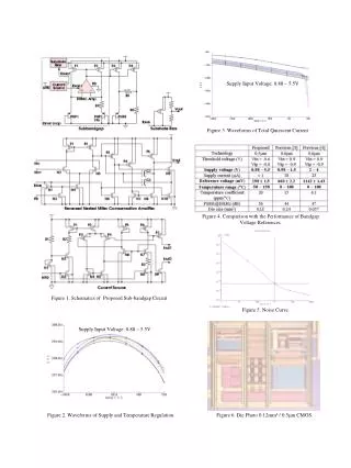
Simulation and Measurement Results • The sub-1V and subthreshold BGR circuit was designed using 0.18μm triple-well CMOS technology. • FF, TT and SS represent the simulated results of the fast, typical and slow process corners at -20°C, 25°C, and 100°C. • the proposed BGR circuit occupying the chip area of 0.029mm2 without pads.
The measured data are the variation of different process corners at room temperature
Comparison of Measurement and data from different process corners for various temperatures at 1V supply voltage
Conclusion • The proposed simple bandgap voltage reference circuit using parasitic NPN transistors without OP’s achieves sub-1V and low-power operation. • The variation of reference voltage is very small for various temperatures, supply voltages and process corners.