Download
1 / 23
230 likes | 356 Views
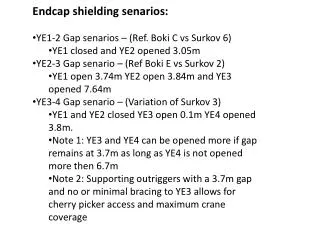
Endcap shielding senarios : YE1-2 Gap senarios – (Ref. Boki C vs Surkov 6) YE1 closed and YE2 opened 3.05m YE2-3 Gap senario – (Ref Boki E vs Surkov 2) YE1 open 3.74m YE2 open 3.84m and YE3 opened 7.64m YE3-4 Gap senario – (Variation of Surkov 3)

E N D
Endcap shielding senarios: • YE1-2 Gap senarios– (Ref. BokiC vsSurkov6) • YE1 closed and YE2 opened 3.05m • YE2-3 Gap senario– (Ref BokiE vsSurkov2) • YE1 open 3.74m YE2 open 3.84m and YE3 opened 7.64m • YE3-4 Gap senario – (Variation of Surkov 3) • YE1 and YE2 closed YE3 open 0.1m YE4 opened 3.8m. • Note 1: YE3 and YE4 can be opened more if gap remains at 3.7m as long as YE4 is not opened more then 6.7m • Note 2: Supporting outriggers with a 3.7m gap and no or minimal bracing to YE3 allows for cherry picker access and maximum crane coverage
ISO view of shielding assembly For guiding into position over beam- pipe Removable third leg for setting on the floor Linear slide for bottom lead plates
Steps of installation Step 1 - Drilling and taping of holes for shielding support Note: This is done after the existing beam pipe is removed Will add a view to show drilling
Step 2 - Install permanent mounts Note: leaving the shielding mounting hardware on YE2 requires a small modification to the spacer disk shielding Will add a view to show permanent mounting features
Step 3 - Installation of the guides The guide post slides into base and is secured with a quick release pin. The guides should be installed for both the external and internal shielding assemblies Base Guide Weight is approximately 10 pounds (5 kg) Rated side force is approximately 310 lbs(140kg)
Step 4 - Adjust pick point on lifting beam Match the pitch of the shield to the pitch of the hall. Pick point slides to adjust Secures pick point to set position
Step 5 - Install and secure external half of shielding assembly ISO view of shielding before installation Note will show ropes/tethers for additional guidance
Step 5 - Continued Isoview of shielding in place.
Step 5 continued - Securing the shielding assembly End view of shielding in place showing cherry picker positions for securing shielding Bottom corner of cherry picker Additional fixtation will be located here
Step 6 - Close the bottom doors Doors must be closed before the second shielding assembly is installed Will show a end view with doors closed
Step 7 - Install and secure IP side of the shielding assembly Repeat steps 4-6 Will add a view showing the second half being installed
Removal Done in reverse order of assembly Note: If additional lead is added after installation, it must be removed to establish the original center of gravity. The pick point of the lifting beam must be returned to its original position for that assembly before removing that assembly
Adapter is required for mounting the to the front of the YE3 disk Adapter for mounting on YE3 Top mount point on YE2
Side view of shielding mounted in YE2-3 gap Will add view
T1 cables and flexible pipes will be pulled back to the external side of the YE4 inner disk The cables and flexible gas and water lines will be disconnected from the IP side of the YE4-outer so it can be moved with the YE4 wall. The cables and flexibleswill be tied back on the external side so that they are not damaged when the shield is installed on the IP side? View of the external side of the YE-4 inner
Side view of shielding in YE3-4 gap Will add view
Strength of M20 fasteners 2xM20 Rx Ry Reacts against the 10mm step of the inner ring 2663 875 2750kg (6050lbs) FS=5.5 w/o 10mm step and nofriction Rx
Plan for testing the shielding assembly Will show shielding mounts being tested by hanging assembly on a fork lift.
Widest part if beam pipe is bracket for vacuum pump at 440mm