Download
1 / 37
400 likes | 927 Views
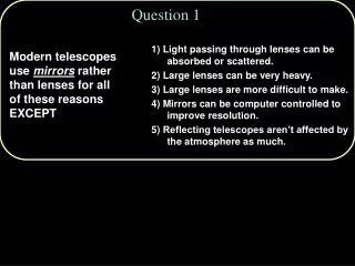
Mirrors & Lenses. Chapter 23. Chapter 23 Learning Goals. Understand image formation by plane or spherical mirrors Understand image formation by converging or diverging lenses. Understand Image Formation by Plane or Spherical Mirrors.

E N D
Mirrors & Lenses Chapter 23
Chapter 23 Learning Goals • Understand image formation by plane or spherical mirrors • Understand image formation by converging or diverging lenses
Understand Image Formation by Plane or Spherical Mirrors • Relate the focal point of a spherical mirror to its center of curvature • Locate the image of a real object and determine if the image is: • Real or virtual • Upright or inverted • Enlarged or Reduced
Flat Mirrors • Use a picture to define the following • image and object ( I & O) • image & object distance ( q & p ) • image & object height ( h’ & h ) • real image • virtual image
Summary of Flat Mirrors • The image is as far behind the mirror as the object is in front of the mirror • The image is unmagnified, virtual, & upright
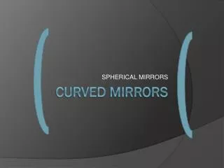
Spherical Mirrors • Two types of spherical mirrors • Concave Mirror • Convex Mirror
Spherical Mirrors • Use a picture to define the following for a concave mirror and convex mirror • principal axis • center of curvature ( C ) • radius of curvature ( R ) • image point and object ( I & O) • image & object distance ( q & p ) • image & object height ( h’ & h )
Spherical Mirrors • When the object is very far from the mirror • The image point is halfway between the center of curvature and the center of the mirror • The image point will be called the focal point • The image distance will be called the focal length
Spherical Mirrors • Magnification Equation M = image height = h’ = - q object height h p
Spherical Mirrors • Mirror Equation 1 + 1 = 2 pq R • Mirror Equation in terms of focal length 1 + 1 = 1 pqf
Front, or real, side R is positive p & q positive incident light ------------- reflected light Back, or virtual, side p & q negative R is negative No light Ray Diagrams (Mirrors)
Ray Diagrams • Steps for Drawing ray diagrams • Ray 1 is parallel to the principal axis & is reflected through the focal point, F • Ray 2 is drawn through the focal point, & reflected parallel to the principal axis. • Ray 3 is drawn through the center of curvature, C, and is reflected back on itself.
Ray Diagrams • The intersection of any two of these rays at a point locates the image
Spherical Abberation • Rays are generally assumed to make small angles with the mirror • When the rays make large angles, they may converge to points other than the image point • This results in a blurred image
Understand image formation by converging or diverging lenses • Know what factors affect the focal length of lenses • Determine by ray tracing: • Location of the image of a real object: • Upright or inverted image • Real or virtual image • Use the thin lens equation to solve problems • Analyze simple situations in which the image formed by one lens is the object for another lens
Thin Lens Shapes • These are examples of converging lenses • They have positive focal lengths • They are thickest in the middle
More Thin Lens Shapes • These are examples of diverging lenses • They have negative focal lengths • They are thickest at the edges
Thin Lenses • Converging Lenses • biconvex • convex-concave • plano-convex
Thin Lenses • Diverging Lenses • biconcave • convex-concave • plano-convex
Front side p positive q negative -------------- incident light Back side p negative q positive ------------- refracted light Ray Diagrams (Lenses)
Sign Convention for Lenses • f is (+) for a converging lens • f is (-) for a diverging lens • R1 & R2 are (+) if the center of curvature is in back of the lens (converging) • R1 & R2 are (-) if the center of curvature is in front of the lens (diverging)
Ray Diagrams (Lenses) • Steps for Drawing ray diagrams • Ray 1 is parallel to the principal axis & is refracted through one of the focal points • Ray 2 is drawn through the center of the lens and continues straight through. • Ray 3 is drawn through the other focal point, & emerges from the lens parallel to the principal axis
Thin Lenses • Thin Lens Equation 1 + 1 = 2 pq R • Thin Lens Equation in terms of focal length 1 + 1 = 1 pqf
Thin Lenses • Magnification Equation M = image height = h’ = - q object height h p
Ray Diagrams for Lenses • Converging Lenses • Object behind the focal point • Object in front of the focal point • Diverging Lenses • Object behind the focal point • Object in front of focal point
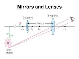
Combination of Thin Lenses • The image formed by the first lens is treated as the object for the second lens
Chapter 23 Resources • http://www.physicsclassroom.com/Class/refrn/U14L5eb.html


![L 33 Light and Optics [3]](https://cdn1.slideserve.com/3393672/l-33-light-and-optics-3-dt.jpg)