Interrupts and reset operations
370 likes | 394 Views
This detailed overview introduces interrupt mechanisms, reset operations, and the significance of interrupts in increasing processor efficiency. Learn about interrupt vectors, sources of interrupts, and the operation of various types of interrupts. Discover how to manage interrupt masks and priorities, including non-maskable and maskable interrupts on the 68HC11 platform.

Interrupts and reset operations
E N D
Presentation Transcript
Overview • Introduction to interrupts • – What are they • – How are they used • 68HC11 interrupt mechanisms • – Types of interrupts • – Interrupt priorities • Resets and their operation/use • Readings: Text, sections 3.6 -- 3.10
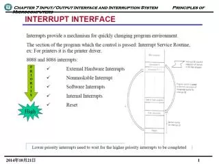
Interrupts: an overview • Mechanism for responding to external events – CPU suspends execution of current routine – Jumps to a special interrupt service routine (ISR) – After executing the ISR, it returns to what it was executing before
Interrupts: an overview • Why use interrupts? ... Efficiency! – Interrupts increase processor system efficiency by letting an I/O device request CPU time only when that device needs immediate attention. – “Main” programs can perform routine tasks without continually polling for I/O device status.
Interrupts: an overview • Interrupts allow the processor to interact with slow devices in an efficient manner – Consider Lab 2: » Required that a counter be updated every second while monitoring a digital input Pseudocode:
Interrupts: an overview Loop: update counter delay check for digital input goto Loop » What about inputs that occur during delay?
Interrupts: an overview – Use a timer that can generate an interrupt » Pseudocode Loop: check for input goto Loop Timer_ISR: update counter reset timer return
Interrupts: an overview • Interrupt Vectors – Interrupt Vector Table located at $FFC0-$FFFF in memory (ROM area) – Each type of interrupt has an entry in the table » Entry contains address of interrupt service routine (16-bit value) » See p.3 of the Programming Reference Guide or Table B-2 in text
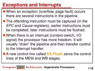
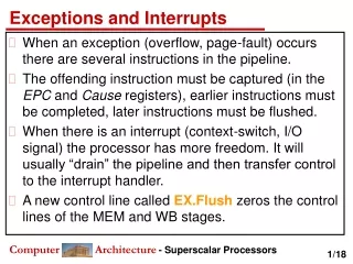
Interrupts: an overview • What happens when an interrupt occurs? – CPU finishes processing current instruction – CPU automatically stacks registers to save the current state of the processor » Pushed onto stack in following order: PC, IY, IX, ACCA, ACCB, CCR – Fetches address of ISR from vector table – Jumps to ISR address
Interrupts: an overview – ISR should end with RTI instruction (Return from Interrupt) » Automatically pulls registers off stack » Returns to original program (using value of PC that was pulled
Interrupts: an overview • Sources of interrupts – I/O » SCI, SPI » Parallel I/O (STRBA) – Timer, pulse accumulator, real-time interrupt – External pins » XIRQ*, IRQ*
Interrupts: an overview – Software interrupt » SWI instruction – Illegal opcode trap – COP failure – Clock monitor – RESET* pin
Interrupts: an overview • Masks and enables – Some interrupts are maskable » If interrupt is masked (or disabled), it will be ignored by the CPU » Can be enabled/disabled by setting bits in control registers – Non-maskable interrupts » Can be used for interrupts that should never be ignored
Interrupts: an overview – I bit in CCR is the interrupt request mask » If set, all maskable interrupts are disabled Use CLI and SEI instructions to clear/set I bit is initially set after system reset » To only mask some interrupts, clear I and set the individual masks in the control registers – X bit in CCR is the XIRQ mask » Masks the XIRQ* pin (non-maskable interrupt) » Initially set after system reset » Software can clear it, but cannot set it
68HC11 interrupts -- 18 in all • Non-maskable -- 3 types • – XIRQ* • » On reset, this interrupt is masked • » During initialization, XIRQ can be enabled using • a TAP instruction (clear the X bit in the CCR) • » Once enabled during initiation, its state will not change • » Used for high priority interrupt sources -- safety
68HC11 interrupts -- 18 in all – Illegal opcode fetch » When an opcode is decoded, if it is invalid, this interrupt will occur » User should write trap routine to deal with the error – Software generated interrupt (SWI) » Instruction SWI behaves like an interrupt » Enables development tools such as breakpoints in Buffalo monitor
68HC11 interrupts -- 18 in all • Maskable -- 15 types – These interrupts are masked as a group by the I bit in the CCR – IRQ* » External pin » Primary off-chip maskable interrupt » Can be set to either low-level or falling-edge sensitive
68HC11 interrupts -- 18 in all Default is level sensitive (IRQE=0 in OPTION register) Edge sensitive can be set within first 64 cycles after reset (IRQE=1 in OPTION register) – Other interrupts based on operation of internal support hardware -- timers, serial I/O, parallel I/O, etc.
68HC11 interrupts -- 18 in all • Interrupt Priority – What if two interrupts occur at the same time? » Interrupts have assigned priority levels PSEL3-0 in HPRIO register can be used to designate highest priority interrupt – Default is IRQ*
68HC11 interrupts -- 18 in all » Higher priority interrupt is serviced first • When CPU recognizes an interrupt, it sets the I bit – Prevents additional interrupts • I bit is restored by RTI » It is possible to clear the I bit in the ISR (CLI instruction) to allow the ISR to be interrupted (nested interrupts) • Usually a bad idea
68HC11 resets • Resetting the processor brings the system up into a known point from which normal operations can be initiated • – Primarily concerned with the initialization of operating conditions and key register values • Similar to interrupt except that registers are not stacked
68HC11 resets • 68HC11 supports 3 types of resets • – Power on or RESET* • » Occurs when a rising edge is detected on input power Vdd (i.e., at power up) or when user asserts the input RESET* line • » Power up reset delays reset actions for 4096 clock cycles to allow clock to stabilize • » RESET* must be held low for 6 clock cycles in order to be recognized (vs. it being used as an output signal)
68HC11 resets – Computer Operating Properly (COP) watchdog timer failure reset » When activated, causes the processor to reset if no activity is detected for a long period of time » Processor must periodically execute code segment to reset the watchdog timer to avoid the reset • Write $55 to COPRST ($103A) followed by writing $AA
68HC11 resets » Examples of use: • System is waiting for sensor input but sensor has failed and will never provide input • EMI may cause interference in fetching instructions/data » Enable the watchdog during initialization operations (NOCOP bit in CONFIG register)
68HC11 resets – Clock monitor reset » Causes a reset if clock frequency drops below 10 kHz » Clock frequencies from 10 kHz to 200 kHz can cause unpredictable reset actions » Once the low frequency clock is detected, system should have ~1000 clock cycles to reset before clock dies completely (based on time constant of crystal)
68HC11 resets • 68HC11 Instructions – RTI -- Return from Interrupt – CLI -- Clear I bit in CCR – SEI -- Set I bit in CCR – WAI -- Wait for Interrupt » Stacks registers and waits for an unmasked interrupt » Reduces power consumption
68HC11 resets – STOP » If S bit in CCR is set, this acts like a NOP » Else • Causes all system clocks to halt • Minimum power standby mode • Registers and I/O pins are unaffected • Can recover with RESET*, XIRQ*, or unmasked IRQ* signal
68HC11 resets Specifying Interrupt Service Routine Addresses – The starting addresses of all interrupt service routines are specified in the jump table at addresses FFC0 -- FFFF -- ROM area in the HC11 – Table contents and thus the ISR addresses must be specified at the time of manufacture
68HC11 resets • – In evaluation units such as the EVBU, we can not change the contents of the ROM jump table (the table had to be completed during manufacture) • » In the table, the ISR starting addresses are specified to be in the RAM area of the memory system • » This RAM area is, in effect, a second “pseudojump table” for user to specify the real ISR starting addresses -- sort of like indirect addressing • Each entry is 3 bytes -- allows for unconditional jump statement to the ISR address
68HC11 resets • » Thus, to use interrupts in your programs, you must • Determine the ISR starting address specified in the jump table at FFC0 • At that specified address in RAM, store the opcode for a JMP instruction followed by the address of the ISR
68HC11 resets • » Table 3-2 in the EVBU manual lists the jump table addresses for the ISRs • WARNING: the addresses in the tables should ALL start with 00 instead of E0. For example, the clock monitor ISR is at addresses $00FD-00FF in RAM
68HC11 resets • Reentrant subroutines • – Any subroutines called by an ISR should be reentrant, especially if used elsewhere in your program • » A “reentrant” subroutine can be called again before it returns from a previous call • – Example: Subroutine to convert 8-bit hex value into 2 ASCII digits • ;****************** • ; Hex_To_ASCII: Calls routine Convert_Nibble to convert 4-bit • ; value to ASCII • ; Input: Hex value in ACCA • ; Output: ASCII digits in ACCA and ACCB • ;******************
68HC11 resets Temp_Storage DS 1 ; temporary result Hex_To_ASCII: TAB ANDB #$0F JSR Convert_Nibble ; result in B STAB Temp_Storage TAB LSRB LSRB LSRB LSRB JSR Convert_Nibble LDAA Temp_Storage RTS – What happens if ISR calls Hex_To_ASCII?
68HC11 resets • Reentrant Subroutines – To make subroutines reentrant, don’t use allocated memory for passing parameters or temporary storage – Use the stack or registers instead ;****************** ; Hex_To_ASCII: Assume Convert_Nibble is also reentrant. ; Input: Hex value in ACCA ; Output: ASCII digits in ACCA and ACCB ;******************
68HC11 resets Hex_To_ASCII: TAB ANDB #$0F JSR Convert_Nibble ; result in B PSHB ; save on stack TAB LSRB LSRB LSRB LSRB JSR Convert_Nibble PULA ; get first result RTS