Interrupts
Interrupts. ELEC 330 Digital Systems Engineering Dr. Ron Hayne Images Courtesy of Ramesh Gaonkar and Delmar Learning. Basic Concepts of Interrupts. An interrupt is a communication process set up in a microprocessor or microcontroller in which:


Interrupts
E N D
Presentation Transcript
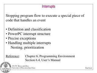
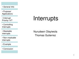
Interrupts ELEC 330 Digital Systems Engineering Dr. Ron Hayne Images Courtesy of Ramesh Gaonkar and Delmar Learning
Basic Concepts of Interrupts • An interrupt is a communication process set up in a microprocessor or microcontroller in which: • An internal or external device requests the MPU to stop the processing • The MPU acknowledges the request • Attends to the request • Goes back to processing where it was interrupted 330_10
Types of Interrupts 330_10
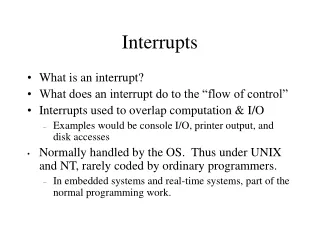
MPU Response to Interrupts • When the interrupt process is enabled, the MPU checks the interrupt request flag just before the end of each instruction. • If the interrupt request is present, the MPU: • Completes the execution of the instruction • Resets the interrupt flag • Saves the address of the program counter on the stack • To restart the execution, the MPU needs to be redirected to the memory location where the interrupt request can be met. • Accomplished by interrupt vectors • The set of instructions written to meet the request is called an interrupt service routine (ISR). • Once the request is accomplished, the MPU should find its way back to the next instruction, where it was interrupted. • Accomplished by a specific return instruction 330_10
PIC18 Interrupts • PIC18 Microcontroller family • Has multiple sources that can send interrupt requests • Does not have any non-maskable or software interrupts • All interrupts are maskable • Has a priority scheme divided into two groups • High priority and low priority • Uses many Special Function Registers (SFRs) to implement the interrupt process 330_10
PIC18 Interrupt Sources • External sources • Three pins of PORTB -RB0/INTO, RB1/INT1,and RB2/INT2 • These pins can be used to connect external interrupting sources such as keyboards or switches • Change in logic levels of pins RB4-RB7 of PORTB can be recognized as interrupts • Internal peripheral sources • Examples: Timers, A/D Converter, Serial I/O, and Low-Voltage Detection Module 330_10
PIC18 Interrupt Sources • Special Function Registers (SFRs) • RCON register sets up global priority. • INTERCON registers deal primarily with external interrupt sources. • PIR, PIE, and IPR handle internal peripheral interrupts. • To recognize the occurrence of an interrupt request, the MPU needs to check the following three bits: • The flag bit to indicate that an interrupt request is present • The enable bit to redirect the program execution to the interrupt vector address • The priority bit (if set) to select priority 330_10
Interrupt Priorities • Any interrupt can be set up as high- or low-priority • High-priority interrupt vector location 000008H. • Low-priority interrupt vector location 000018H. • A high-priority interrupt can interrupt a low-priority interrupt in progress. • The interrupt priority feature is enabled by Bit7 (IPEN) in RCON register. 330_10
External Interrupts • INTERCON Register • INTCON2 Register • INTCON3 Register 330_10
Interrupt Service Routine (ISR) • Similar to a subroutine • Attends to the request of an interrupting source • Clears the interrupt flag • Should save register contents that may be affected by the code in the ISR • Must be terminated with the instruction RETFIE • When an interrupt occurs, the MPU: • Completes the instruction being executed • Disables global interrupt enable • Places the address from the program counter on the stack 330_10
Interrupt Service Routine (ISR) • RETFIE [s] ;Return from interrupt • If s =1, the MPU also retrieves the contents of W, BSR, and STATUS register before enabling the global interrupt bit. • In high-priority interrupts: • The contents of W, STATUS, and BSR registers are automatically saved into respective shadow registers. • RETFIE 1 (or RETFIE FAST) retrieves the contents of these registers. • In low-priority interrupts: • These registers must be saved as a part of an ISR if these registers are affected by the code in the ISR. 330_10
Internal Interrupts • The PIC18 MCU includes many internal devices such as the timers and the A/D converter that can interrupt the MPU. • Each interrupt is associated with three bits • Priority, interrupt request flag, and enable (similar to the that of external interrupts) • Registers associated with the internal interrupts • IPR: Interrupt Priority Register • PIE: Peripheral Interrupt Enable • PIR: Peripheral Interrupt Request (Flag) 330_10
Interrupt Registers • IPR1 • PIE1 • PIR1 330_10
Multiple Interrupt Sources • In PIC18 MCU, all interrupt requests are directed to one of two memory locations: • 000008H (high-priority) • 000018H (low-priority) • When multiple requests are directed to these locations, the interrupt source must be identified by checking the interrupt flag through software instructions. 330_10
Illustration • Problem Statement • Set up INT1 as a high-priority interrupt • Set up Timer1 and Timer2 as low-priority interrupts 330_09
Illustration 330_04
Illustration 330_04
Illustration 330_04