Trigger Matrix
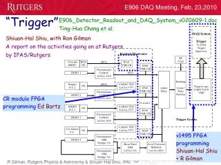
Trigger Matrix. Shiuan-Hal. Trigger. trigger supervisor. y h o d o s c o p e. x h o d o s c o p e. (“times 4”). level 2 v1495. TRIGGER. μ. level 1 v1495. discriminator. level shifter. Compare with E866 trigger system. Replaced by v1495. TERM OR. TRIG S4XY

Trigger Matrix
E N D
Presentation Transcript
Trigger Matrix Shiuan-Hal
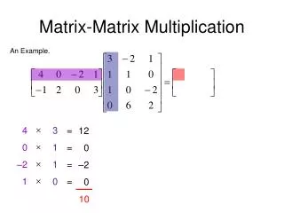
Trigger trigger supervisor y h o d o s c o p e x h o d o s c o p e (“times 4”) level 2 v1495 TRIGGER μ level 1 v1495 discriminator level shifter
Compare with E866 trigger system Replaced by v1495
TERM OR TRIG S4XY AND134
E866 Trigger matrix • Using the fast monte carlo simulation data. And make cut which listed below. • Only using station 1,2,4 hodoscope. • Ignore all the track crossing X=0(The muon was bended in Y-direction in E866) • Restrict the positive muon go to upper side, and negative muon go quite the other way in first station. • Confine the simulation muon come from the target and not from the dump.
E906 VS. E866 trigger system • E906 • Made up by VME FPGA modules • Common stop • Maxium 300ns from RF to trigger output • Look up table was build in FPGA • E866 • Made up by CAMAC and NIM logic modules • Common start • 91ns from RF to trigger output • Look up table was build in memory chip.
E906 Trigger system hardware limit • 128 input channels with 1 ns resolution and 128 ns adjustable delay. • The latency from input to output is about (5x4=20)+?? ns. The latency will less then 150ns now for each v1495. Each pipeline step only cost 4ns now, and we have only 5 layers pipeline in our design. The “??” here means the latency from input to the trigger matrix pipeline which we are still not measure. • From a simple muon track simulation in bend plane, we found there are almost 1400 track conditions will appear for a positive muon. It means 2800 tracks need to deal in one v1495, and may cost about 9000 logic elements.
E906 Trigger matrix current situation • In band plane v1495 • Bit 1 on – if a triplet was a positive muon with a Ptxmax<0.6 GeV • Bit 2 on – if a triplet was a positive muon with a Ptxmax<0.9 GeV …….. • Bit 8 on – if a triplet was a positive muon with a Ptxmax<2.7 GeV • Bit 9 on – if a triplet was a negative muon with a Ptxmax<0.6 GeV • Bit 10 on – if a triplet was a negative muon with a Ptxmax<0.9 GeV …….. • Bit16 on – if a triplet was a negative muon with a Ptxmax<2.7 GeV. • In non-band plane v1495 • Still under discussion. • Maybe need to add the information of the number of fired paddle.
E906 Trigger matrix current situation • Target Dimuon, good momentum • Dump Dimuon • Other Dimuon • Single target muon • Single non-target muon • At least one quadrant indicates track • 3/4 planes hit in at least 2/4 front end FPGAs