Download
1 / 16
170 likes | 324 Views
GROUNDWATER HYDROLOGY II. WMA 302 Dr. A.O. Idowu , Dr. J.A. Awomeso and Dr O.Z. Ojekunle Dept of Water Res. Magt . & Agromet UNAAB. Abeokuta. Ogun State Nigeria oojekunle@yahoo.com. STEADY STATE FLOW AND TRANSIENT FLOW.

E N D
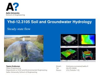
GROUNDWATER HYDROLOGY II WMA 302 Dr. A.O. Idowu, Dr. J.A. Awomeso and Dr O.Z. Ojekunle Dept of Water Res. Magt. & Agromet UNAAB. Abeokuta. Ogun State Nigeria oojekunle@yahoo.com
STEADY STATE FLOW AND TRANSIENT FLOW • Steady-state flow occurs when at any point in a flow field the magnitude and direction of the flow velocity are constant with time. • Transient flow (Unsteady flow or non steady flow) occurs when at any point in a flow field the magnitude or direction of the flow velocity changes with time.
STEADY STATE FLOW AND TRANSIENT FLOW (Cont) • Fig. 1 below show a steady-state flow groundwater flow pattern (dashed equipotentials, solid flowline) through a permeable alluvial deposit beneath a concrete dam. Along the line AB, the hydraulic head hAB = 1000m. It is equal to the elevation of the surface of the reserviour above AB. Similar hAB = 900m (the elevation of the tailrace pond above CD). The hydraulic head drop h across the system is 100m. if the water level in the reserviour above AB and the water level in the tailrace pond above CD do not change with time. The hydraulic head at point E, for example, will be hE = 950m and will remain constant. Under such circumstances the velocity V = -Kdh/dl will also remain constant through line. In a steady-state flow system, the velocity may vary from point, but it will not vary with time at any given point.
STEADY STATE FLOW AND TRANSIENT FLOW (Cont) • Let us now consider the transient flow problem schematically shown in fig. 2. At time t0 the flow net beneath a dam will be identical to that of fig. 1 and the hE will be 950m. If the reserviour level is allowed to drop over the period t0 to t1 until the water level above and below the dam are identical at time t1, the ultimate condition under a dam will be static with no flow of water from the upstream to the down stream side. At point E the hydraulic head hE will under a time-dependent decline from hE = 950m at time t0 to its ultimate value of hE= 900m. There may well be time lag in such a system so that hE will not necessarily reach the value hE = 900m until sometime at t = t1.
DIFFERNCES BETWEEN STEADY STATE FLOW AND TRANSIENT FLOW • One important difference between steady and transient lies in the relation between their flowline and pathlines. Flowlines indicate the instantaneous direction of flow throughout a system (at all times in a steady system, or at a given instant in time in a transient system). They must be orthogonal to the eqiuipotential lines throughout the region of flow at all times. Pathlines may take the route that an individual particle of water follows through a region of flow during a steady or transient event. In a steady flow system, a particle of water enter the system at an inflow boundary will flow towards an outflow boundary along a pathline that coincides with with a flowline such as that shown in fig. 1. In Transient system, on the otherhand, pathline and flowline do not coincide. Although a flow net can be constructed to describe the flow conditions at any given instant in line in a transient system, the flowline shown in such a snapshot represent only the configuration of the flowlines changes with time, the flowlines cannot describes, in themselves, the complete path of a particle of water as it transerves the system. The delineation of transient pathline has obvious importance in a study of groundwater contamination.
Note • The practical methodology that is presented later is often based on theoretical equations, but it is not usually necessary for practicing hydrogeologist to have the mathematical equations at his/her fingertips. The primary application of steady state techniques in groundwater hydrology is the analysis of regional groundwater flow. An understanding of transient flow is required for the analysis of well hydraulic, groundwater recharge, and many of the geochemical and geotechnical application.
STEADY-STATE SATURATED FLOW • Consider a unit volume of porous media such as that shown in fig. 3 such an element is usually called an elemental control volume. The law of conservation of mass for a steady-state flow through a saturated porous medium requires that the rate of fluid mass flow into any elemental control volume. The equation of continuity that translate the law into mathematical form can be written with reference to fig. 3 as
STEADY-STATE SATURATED FLOW (Cont) • A quick dimension analysis on the v terms will show then to have the dimension of a mass rate of flow across a unit cross-sectional area of the elemental control volume. If the fluid is incompressible, (x,y,z) = constant and the ’s can be removed from eqn 1. even if the fluid is compressible and (x,y,z) is not equal constant, it can be shown that the terms of the form dvx/dx are much greater that terms of the form vxd/dx, both of which arise when the chain rule is used to expand eqn 1 in either case eqn 1 simplifies to
STEADY-STATE SATURATED FLOW (Cont) • Substitution of darcy’s law for Vx, Vy and Vz in eqn. 2 yield the equation of flow for steady-state flow through anisotropic saturated porous medium. • For an anisotropic medium, Kx=Ky=Kz, and if the medium is also homogeneous, then k(x,y,z)=constant. Eqn. 3 then reduces to the equation of flow for steady-state flow through a homogeneous isotropic medium.
STEADY-STATE SATURATED FLOW (Cont) • Eqn. 4 is one of the most basic partial differential equation to mathematician. It is called laplace’s equation. The solution of the equation is a function of h(x,y,z) that describes the value of hydraulic head h at any point in a three dimensional flow field. A solution of equation 4 allows us to produce a contoured equipotential map of h1 and with the addition of flowline, at a flow net. • For steady-state saturated flow in a two dimension flow field, say in the xz plane, the central term of eqn. 4 would drop out and the solution would be a function of h(x,z).
TRANSIENT SATURATED FLOW • The law of conservation of mass for transient flow in a saturated porous medium requires that the net rate of fluid mass flow into any elemental control volume be equal to the time rate of change of fluid mass storage with the element with reference to fig 3, the equation of continuity takes the form
TRANSIENT SATURATED FLOW (Cont) • The first term on the right hand side of eqn. 6 is the mass rate of water produced by the expansion of water under a change in its density . The second term is the mass rate of water produced by the compaction of the porous medium as reflected by the change in its porosity n. The first term is controlled by the compressibility of the fluid and the second term is controlled by the compressibility of the aquifer . It is necessary to simplify the second terms in the right of equation 6. We known that the change in and the the change in n are both produced by the change in hydraulic head h, and that the volume of water produced by the 2 mechanisms for a unit decline in head in Ss, where Ss is the specific storage given by Ss = g ( + n). The mass rate of water produce (time rate of change of fluid mass storage) is Ssdh/dt and the eqn. 6 becomes