Download
1 / 36
360 likes | 476 Views
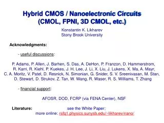
Hybrid CMOS / Nanoelectronic Circuits (CMOL, FPNI, 3D CMOL, etc.). Konstantin K. Likharev Stony Brook University Acknowledgments: - useful discussions : P. Adams, P. Allen, J. Barhen, S. Das, A. DeHon, P. Franzon, D. Hammerstrom,

E N D
Hybrid CMOS / Nanoelectronic Circuits (CMOL, FPNI, 3D CMOL, etc.) Konstantin K. Likharev Stony Brook University Acknowledgments: - useful discussions: P. Adams, P. Allen, J. Barhen, S. Das, A. DeHon, P. Franzon,D. Hammerstrom, R. Karri, R. Kiehl, P. Kuekes, J. H. Lee, J. Li, X. Liu, J. Lukens, X. Ma, A. Mayr, C. A. Moritz, V. Patel, D. Resnick, N. Simonian, G. Snider, S. V. Sreenivasan, M. Stan, D. Stewart, D. Strukov, Z. Tan, W. Wang, R. Waser, R. S. Williams, T. Zhang - financial support: AFOSR, DOD, FCRP (via FENA Center), NSF Literature:see the White Paper; more online: rsfq1.physics.sunysb.edu/~likharev/nano/ ITRS ERD July 2008
add-on top nanowire level similar two-terminal nanodevices at each crosspoint CMOS stack bottom nanowire level I ON state -Vt OFF state V 0 ON state V- +Vt V+ CMOS/NANO HYBRIDS: THE IDEA Historic (first?) version: (J. Heath, P. Kuekes, G. Snider, R. S. Williams 1998) Basic current version: ITRS ERD July 2008
RELATION TO DEVICE TECHNOLOGIES DISCUSSED TODAY Nanoscale DevicesApplicability to CMOL/FPNI NEMS switches2-terminal switches OK Spin torque transfer devices STT junctions may be OK Carbon-based devices n/a Atomic / electrochemical metal switches OK Collective spin devices n/a Single electron devices latching switch OK ___________________________________________________________ + Phase-change cells + Organic layers (with and w/o embedded clusters) ITRS ERD July 2008
state 1 I -Vt 0 1 state 0 V 0 1 0 state 1 V- +Vt V+ BISTABLE TWO-TERMINAL DEVICES (a.k.a. latching switches, a.k.a. programmable diodes) DC I-V curve (schematically):Several material options demonstrated: - polymers (with or w/o clusters) - metal oxides (or sulfides) - solid electrolytes - amorphous silicon - chalcogenides - molecular SAMs A few examples: L. Bolzano et al. (2004) Aluminum tris(8-hydroquinoline) Y.-S. Lai et al. (2005) Poly(N-vinylcarbazole) R. T. Weitz et al. (2006) Copper-2,3-dichloro-5,6-dicyano-p-benzoquinone ITRS ERD July 2008
OFF ON METAL-OXIDE LATCHING SWITCHES “Memory effects” in oxides have been known for a while: G. Dearnaley et al.,Rev. Prog. Phys. (1970): a review with 150+ references Just a few recent references: metal: S. Seo et al.,APL (2003) Ni B. J. Choi et al.,JAP (2005) Ti H. Sim et al.,Microel. Eng. (2005) Nb D. Lee et al., EDL (2005) Zr A. Chen et al., IEDM’05 Cu M. Kund et al., IEDM’05 Ag D. C. Kim et al., APL (2006) Nb N. Banno et al., IEICE TE (2006) Cu(S) T.-N. Fang et al., ICMTD’07 Cu L. Courtade et al., ICMTD’07 Ni W. Guan et al., APL (2007)Zr S.-W. Kim & Y. Nishi, NVMTS’07 Cu(S) D. Stewart, NVMTS’07 Ti K.-C. Liu et al., NVMTS’07 Hf D. Lee et al., APL (2007) Mo Just a few examples: B. J. Choi et al. (2005) A. Chen et al. (2005) D. Lee et al. (2007) With time, data are becoming more reproducible: TE Cu2O Cu ITRS ERD July 2008 A. Chen et al. (IEDM’05)
RECENT RESULTS: Si /α-Si / M JUNCTIONS Y. Dong et al., 2008 S. H. Jo and W. Lu, 2008 ITRS ERD July 2008
NANOWIRE CROSSBARS W. Wu et al. (2005) [HPL] crossbar with Fnano = 15 nm G.-Y. Jung et al. (2006) [HPL + Caltech] ITRS ERD July 2008 J. Green et al. (2007) [Caltech + UCLA]
ADVANCED LITHORGAPHIES Nanoimprint EUV IL Block-copolymer IMPRIO 1100 from Molecular Imprints, Inc. (“sub-50nm”) www.zeiss.com B. Wua and A. Kumar (2007) crossbar with Fnano = 15 nm ITRS ERD July 2008 J. Green et al. (2007) www.almaden.ibm.com
nanodevices (latching switches) interface via (“pin”) gold nanowire levels (nanoimprint) interface pins CMOS stack (just a cartoon) MOSFET Si wafer K. L. (2004) “CMOL” INTERFACE CONCEPT (I) ITRS ERD July 2008
SILICON PIN ARRAYS (developed mostly for field emission) http://my.ece.ucsb.edu/mishra/ vacuummicroelec/progressb.0157.htm http://www.oxfordplasma.de/ process/sibo_wtc.htm Tip radii 2-10 nm Main challenge: Move to the back end of the CMOS process flow (metals?) ITRS ERD July 2008
(a) (b) (c) (d) (e) (f) POSSIBLE CMOL FABRICATION FLOW ITRS ERD July 2008 K. L. (2007a)
CMOL INTERFACE CONCEPT (II) Most important feature: pin array tilt by angle = arcsin(Fnano/FCMOS) = arctan(1/r) pin 1 pin 2A 2FCMOS 2rFnano A B pin 2B 2Fnano Every nanowire (and hence every crosspoint) may be addressed from CMOS! ITRS ERD July 2008 K. L. (2004, 2005); D. Strukov and K. L. (2006)
CMOL: YIELD WITHOUT ALIGNMENT Shift along the top level: fine finebad?bad!fine fine Shift along the bottom level: fine finebad!fine fine fine Theoretical yield maximum: 100% ITRS ERD July 2008 K. L. (2007)
block address decoder block block block data Acol1 block block block Arow2a select Arow1 block block block select Arow2b ECC unit select block row address data I/O cell addresses Acol2 barrel shifter external address mapping table data (r2 lines) data Acol1 Arow1 Arow1 select data decoder Acol1 memory cell array Rpd Arow2 select select decoder Arow2 select decoder data decoder Acol2 data address control CMOL array data lines data I/O data in/out barrel shifter Acol2 RESISTIVE MEMORIES: ARCHITECTURE Top-level structure: Limited data granularity: CMOL block: CMOS cell: Barrel shift decoder: ITRS ERD July 2008 D. Strukov and K. L. (2007a)
sense amplifier buffer RESISTIVE MEMORIES: EVALUATION RESULTS Equivalent circuit for readout delay calculation: Final results example: density and defect tolerance 10 Total chip area optimization: Bottom line: - density up to 1 Tb/cm2 feasible (see below) - speed, power OK - defect tolerance acceptable (~10%) ITRS ERD July 2008 D. Strukov and K. L. (2007a)
(b) CMOS row 1 VDD input nanowire CMOS inverter (c) CMOS row 2 A B F (a) A 2βFCMOS 2βFCMOS2(r - 1) output nanowire α CMOS column 1 CMOS column 2 B A B nanodevices RON F F Cwire Rpass CMOS inverter pass transistor RECONFIGURABLE LOGIC CIRCUITS Generic CMOL fabric ITRS ERD July 2008 D. Strukov and K.L. (2005)
(a) b31 b30 b1 b0 a31 a30 a1 a0 (b) s1 s0 s31 s30 CMOL FPGA CIRCUIT: EXAMPLE …mapped on the CMOL fabric… INPUT 31 0 …before… OUTPUT ai bi (gil, pil) (gjl, pjl) pi0 ci gil (gil, pil) si ci=gil+1 (gi0, pi0) (gil+1, pil+1) 32-bit Kogge-Stone adder… …and after reconfiguration (@ 50% of bad devices) ITRS ERD July 2008 D. Strukov and K.L. (2005)
CMOL FPGA: RESULTS (I) defect tolerance.. ..and performance FCMOS = 45 nm 32 nm 22 nm FCMOS= 32 nm, Fnano= 9 nm: A 110 m2, 0.9 ns Bottom line: yield >99% for 22-25% (!) of bad devices CMOS FPGA with the same FCMOS: A 70,000 m2, 1.7 ns ITRS ERD July 2008 D. Strukov and K.L. (2005)
Latched CMOL fabric: tile boundary basic cell latch cell 2Fnano 2aFnano CMOS latch 4FCMOS in out CMOL FPGA CAD 1.0 Design flow: Input circuit blif format SIS: Technology (NOR gate and latch) mapping Circuit pre-processing Defective cells Initial value of N Heuristic placement Decrease N Increase N N = 0 Global router countmax < T-N -∆ countmax > T-N otherwise Exit without success Exit with success Latch cell: First goal: Toronto 20 benchmark circuit set ITRS ERD July 2008 D. Strukov and K.L. (2006a)
CMOL FPGA: RESULTS (II) Toronto 20 benchmark circuit set ITRS ERD July 2008 D. Strukov and K.L. (2006a)
DIGITAL CMOL: PROSPECTS (I) ITRS ERD July 2008 K. L. and D. Strukov (2007)
DIGITAL CMOL: PROSPECTS (II) ITRS ERD July 2008 K. L. and D. Strukov (2007)
-window F T pixel (output) N S plane (input) F N SAMPLE DSP TASK: CONVOLUTION (e.g., for FPA image processing) Parameters selected for our estimates: N = 1,024 F = 32 (i. e. << N) Accuracy: nS = n = 12 Demands to hardware: Add-multiplies: F2N2 109 per frame CMOS μ-processor: ~ 100 ms per frame ITRS ERD July 2008 D. Strukov and K. L. (2007b)
IN ~CN ON CN clk clk ~CE IW in out OE CE CW OW IE ~CW OS ~CS CS IS TWO NEW CELLS: Control cell: New (programmable) latch: output pin added CMOS line for control logic gnd Vdd input pin (not used) 8 FCMOS ITRS ERD July 2008 Footprint: (3×8FCMOS)2
S 12 bits in in in out out out Programmable latch cell Basic cell Control cell used φ (12 bits) used not used 12 bits not used other not used 12-bit Wallace Tree Multiplier (Partial Product Generation and Reduction) cA cB 0 1 1 0 32-bit Kogge Stone Adder 24 bits M 24 bits 1 2 0 in in in 0 out out out cM 32 bits 1 0 T 32 bits in in in out out out cT multiplexer multiplier adder ARCHITECTURE AND PERFORMANCE Calculated performance for N = 1,024, F = 32, n = 12 bits: ~ 25 μs, vs. ~3,500 μs for CMOS (per frame) ITRS ERD July 2008 D. Strukov and K. L. (2007b)
+ - soma j wij jk+ j i + - soma k jk- NEUROMORPHIC NETWORKS (“CROSSNETS”) Basic idea: CMOS “somas” + nanowire “axons” and “dendrites” + nanodevice “synapses” wjk = {-1, 0, +1} Generic structure of a feedforward CrossNet ITRS ERD July 2008 S. Fölling et al. (2001) O. Turel et al. (2004)
CROSSNETS: PERFORMANCE ESTIMATES (@ 33 nanodevices per synapse, Fnano= 3 nm, connectivity104): Synapse footprint: ~ 500 nm2 Synapse density: ~ 21011 cm-2 (> 1012 cm-2 bits/cm2) Neural cell density: ~ 5107 cm-2 (cf. 1.5107 cm-2 in bio) Intercell latency: ~ 20 ns @ 100 W/cm2 (R ~ 1010 ) or: ~ 2,000 ns @ 1 W/cm2(R ~ 1012 ) (cf. ~10 ms in bio) CMOL is the first hardware capable of challenging human’s cerebral cortex ITRS ERD July 2008 Ö. Türel et al. (2004)
ITRS ERD July 2008 From: T. Hynton (DARPA), March 2008
ANOTHER CMOL SPECIES: HPL’s FPNI G. Snider and R. S. Williams (2007) ITRS ERD July 2008
WEI WANG’s “3D CMOL” Features: - simpler interface pins - twice smaller area ITRS ERD July 2008 D. Tu et al. (2007)
SINGLE-ELECTRON LATCHING SWITCH: POSSIBLE MOLECULAR IMPLEMENTATION perylenediimide group as a single-electron trap island (C6H13-) non-conducting support group OPE bridges as tunnel junctions naphthalenediimide group as a single-electron transistor island isocyanide attachment group Andreas Mayr (SBU) in: K. Likharev et al. (2003) ITRS ERD July 2008
NDR IN MOLECULAR-SCALE SETs theoretical result… …and experiment NDR! S. Khondaker et al. (2004) N. Simonian, J. Li, and K. L. (2007) i.e. current is determined by the highest barrier (giving the lowest tunneling rate) NDR effect: unexpected, but in the hindsight, natural: one barrier suppressed, another enhanced current drops! Vsd = 0: eVsd ~ U: ITRS ERD July 2008
1 VBIAS VOUT VCLK1 Vgnd 3 VIN1 VCLK2 VIN2 Vgnd 2 VCLK1 Vgnd 1 3 2 REF EVAL clock REF phase 1 t 0 I EVAL phase 2 t 0 OFF phase 3 t 0 OFF phase 4 VDD Vt V 0 t 0 NDR CMOL CONCEPT Latching to Boolean “1” Logic gates Goto pair Four-phase clocking upper layer nanowire VCLK lower layer nanowire VGND ITRS ERD July 2008 D. Strukov and K.L. (2007c)
Toronto 20 benchmark set NDR CMOL (preliminary results) Pros Different logic gates Small cell area (×3↑) Nanoscale latch (×1.5↑) Cons Low fan-in Dual rail logic (×2↓) Low fan-out (×1.15↓) Pipeline buffers (×1.25↓) Early summary (compared to CMOL FPGA) Area Comparable Delay Comparable Defect tolerance Comparable Data throughput Much better Better architecture possible? ITRS ERD July 2008 D. Strukov and K.L. (2007c)
CONCLUSIONS CMOS/Nano Hybrids: - possibly, the only way to go beyond the conventional lithography limits - realistic components, demos above ~15 nm Possible Impact: - extending Moore’s Law for 10 to 15 years beyond ITRS 32 nm point - eventually, first challenge to the cerebral cortex Hardware Issues: - Fnano > 10 nm: integration / reproducibility - Fnano < 10 nm:everything: - devices (SAM?) - patterning EUV IL? block-copolymer? - back-end-compatible pins Software Issues: - ASIC performance (vs CMOS) - tolerance to various defects - advanced information processing tasks and methods need better CAD tools ITRS ERD July 2008
THANK YOU! comments/suggestions to: klikharev@notes.cc.sunysb.edu ITRS ERD July 2008