Download
1 / 27
340 likes | 589 Views
MENA 3200 Energy Materials Materials for Electrochemical Energy Conversion Part 3 Materials for SOFCs and PEMFCs Truls Norby. Overview of this part of the course. What is electrochemistry? Types of electrochemical energy conversion devices Fuel cells, electrolysers, batteries

E N D
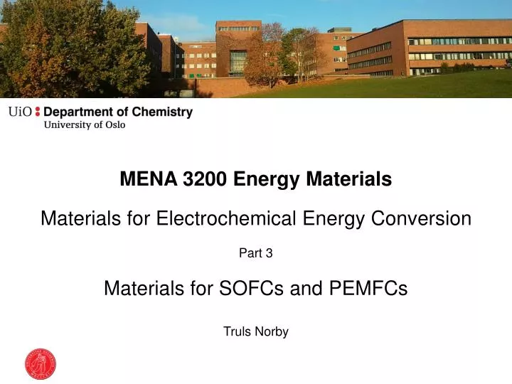
MENA 3200 Energy Materials Materials for Electrochemical Energy Conversion Part 3 Materials for SOFCs and PEMFCs Truls Norby
Overview of this part of the course • What is electrochemistry? • Types of electrochemical energy conversion devices • Fuel cells, electrolysers, batteries • General principles of materials properties and requirements • Electrolyte, electrodes, interconnects • Conductivity • Catalytic activity • Stability • Microstructure • Examples of materials and their properties • SOFC, PEMFC, Li-ion batteries
R Solid Oxide Fuel Cell (SOFC) • “oxide” reflects that the electrolyte is an oxide and that it conducts oxide ions • Electrode reactions Anode(-): 2H2 + 2O2- = 2H2O + 4e- Cathode(+): O2 + 4e- = 2O2- • Operating temperature: 600-1000°C • Fuel: H2 or reformed carbon-containing fuels • Potential advantages: • Fuel flexibility and tolerance • Good kinetics – no noble metals needed • High value heat • Current problems: • High cost • Lifetime issues 4e- + 2O2- O2 2H2 2H2O Solid Oxide Fuel Cell (SOFC)
Typical SOFC designs SOFCs for vehicle auxiliary power units
SOFC electrolyte material requirements • Oxide ion conductivity > 0.01 S/cm • Film of <10 μm gives <0.1 Ωcm2ofresistance or <0.1 V loss at 1 A/cm2 • Ionic transport number >0.99 • Gastight • Tolerate both reducing (H2) and oxidising (air/O2) atmospheres • Be compatible with both electrodes (TEC and chemistry)
Oxide ion conductors • Oxygen vacancies • Obtained by acceptor dopants • Y-doped ZrO2 (YSZ), Sc-doped ZrO2 • Gd-doped CeO2 (GDC) • Sr+Mg-doped LaGaO3 (LSGM) • Disordered inherent oxygen deficiency • Example: δ-Bi2O3 • Oxygen interstitials • No clearcut examples…
Y-stabilised zirconia; YSZ • Doping ZrO2 with Y2O3 • Stabilises the tetragonal and cubic structures • Higher symmetry and oxygen vacancy mobilities • Provides oxygen vacancies as charge compensating defects • Oxygen vacancies trapped at Y dopants • 8 mol% Y2O3 (8YSZ): highest initial conductivity • 10 mol% Y (10YSZ): highest long term conductivity • Metastable tetragonal zirconia polycrystals (TZP) of 3-6 mol% Y2O3 (3YSZ, 6YSZ) gives transformation toughened zirconia – better mechanical properties but lower conductivity • Partially replacing Y with Sc and Yb gives less trapping and better strength
SOFC anode materials requirements • Electronic conductivity > 100 S/cm • Ionic transport as high as possible to spread the reaction from 3pb to the entire surface • Porous • Tolerate reducing (H2) atmospheres • Be compatible with electrolyte and interconnect (TEC and chemistry) • Catalytic to electrochemical H2 oxidation • For carbon-containing fuels: • Be moderately catalytic to reforming and catalytic to water shift • Not promote coking • Tolerant to typical impurities, especially S
SOFC anodes: Ni-electrolyte cermet • Made from NiO and e.g. YSZ • NiO reduced in situ to Ni • Porous • All three phases (Ni, YSZ, gas) of approximately equal volume fractions and form three percolating networks. • Electrons • Ions • Gas • In addition, Ni is permeable to H, further enhancing the spreading of the reaction sites • Electrochemical oxidationof H2 is very fast • Problems • Mechanical instability by redox and thermal cycles • Sulphur intolerance • Too high reforming activity. Tendency of coking • Remedies • Oxide anodes? (Donor doped n-type conductors)
SOFC cathode materials requirements • Electronic conductivity > 100 S/cm • Ionic transport as high as possible to spread the reaction from 3pb to the entire surface • Porous • Tolerate oxidising (air/O2) atmospheres • Be compatible with electrolyte and interconnect (TEC and chemistry) • Catalytic to electrochemical O2 reduction • Must tolerate the CO2 and H2O-levels in ambient air • Too basic materials (high Sr and Ba contents) may decompose under formation of carbonates or hydroxides
SOFC cathodes: Sr-doped LaMnO3 (LSM) • For example La0.8Sr0.2MnO3 (LSM) • p-type electronic conductor: [SrLa/] = [h.] • Active layer is a “cercer” composite with electrolyte • Porous • All three phases (LSM, YSZ, gas) of approximately equal volume fractions and form three percolating networks. • Electrons • Ions • Gas • In addition, LSM is somewhat permeable to O (by mixed O2- and e- conduction), further enhancing the spreading of the reaction sites • Problems and remedies • Sensitive to Cr positioning from interconnect; coat interconnect and reduce operating temperature • Too little mixed conductivity; replace Mn with Co; LaCoO3 has more oxygen vacancies than LaMnO3.
Tomography of the three percolating phases G.C. Nelson et al., Electrochem. Comm., 13 (2011) 586–589.
Anode-supported SOFC membrane electrode assembly (MEA) T. Van Gestel, D. Sebold, H.P. Buchkremer, D. Stöver, J. European Ceramic Society, 32 [1] (2012) 9–26.
SOFC interconnect materials requirements • Electronic conductivity > 100 S/cm • Ionic transport number < 0.01 to avoid chemical shortcut permeation • Gas tight • Tolerate both reducing (H2) and oxidising (air/O2) atmospheres • Be compatible with anode and cathode electrode materials (TEC and chemistry) • Mechanical strength
SOFC interconnects • Ceramic interconnects • Sr-doped LaCrO3 • p-type conductor: [SrLa/] = [h.] • Problems: • Very hard to sinter and machine; expensive • Non-negligible O2- and H+ conduction; H2 and O2 permeable • Metallic interconnects • Cr-Fe superalloys, stainless steels; Cr2O3-formers • Very good electrical and heat conduction • Mechanically strong • Problems: • Oxidation, Cr-evaporation • Remedies: • Reduce operation temperature
Polymer Electrolyte Membrane (PEM)Proton Exchange Membrane (PEM) PEM Fuel Cell (PEMFC) • Electrode reactions Anode(-): 2H2 = 4H+ + 4e- Cathode(+): O2 + 4H+ + 4e- = 2H2O • Operating temperature: 80°C • Fuel: Pure H2 • Advantages: • Robust materials • Challenges: • High cost of membrane and Pt catalyst • Carbon oxidation • Low value heat – heat exchange / cooling difficult • Water management
PEMFC electrolyte material requirements • Proton conductivity > 0.1 S/cm • Ionic transport number >0.99 • Gastight • Tolerate both reducing (H2) and oxidising (air/O2) atmospheres
Polymer proton conductors • Nafion® • Perfluorinated backbone • Grafted • Sulfonated • Neutralised by NaOH; Na+ • Proton exchanged; H+ • Swelled with water • Hydrophobic framework • Channels with hydrophilic walls • Protolysis to form H3O+ in the water phase • Transport of H+ drags ca. 6 H2O molecules • Backdraft of water
PEMFC electrode materials requirements • Electronic conductivity • Catalytic activity at largest possible electrode-electrolyte interface • Porous to allow gas access • Tolerate reducing (H2, anode) and oxidising (O2, cathode) conditions
PEMFC electrode materials and structures • Carbon papers • Graphite • Carbon nanoparticles • Catalyst nanoparticles • Soaked with electrolyte • Porous gas diffusion layer
PEM electrode materials and structures • Noble metal nanoparticles dispersed on nanostructured carbon supports • Decreases noble metal loading • Challenge: Agglomeration of nanoparticles reduces activity • Challenge: Cathode carbon is oxidised by O2 if no current is drawn.
PEMFC interconnect materials requirements • Electronic conductivity > 100 S/cm • Ionic transport number < 0.01 to avoid chemical shortcut permeation • Gas tight • Tolerate both reducing (H2) and oxidising (air/O2) atmospheres • Be compatible with electrode and electrolyte materials, notably acidity of electrolyte • Mechanical strength
PEMFC interconnects • Graphite interconnects • Pure graphite • Composites • Light weight • Metallic interconnects • Commercial stainless steels • Very good electrical and heat conduction • Inexpensive • Mechanically strong • Problems: • Oxidation in contact with electrolyte
Electrolysersvs fuel cells • In an electrolyser, the product of a fuel cell (H2O, possibly also CO2) is fed… • …the process forced backwards to produce primarily H2 and O2 • H2 may in turn reduce CO2 to form CO… • The same materials and structures may be used, but: • In a fuel cell, the chemical potential gradient is decreased due to losses – less severe materials requirements compared to equilibrium • In an electrolyser, the chemical potential gradient is increased to overcome the losses – more severe materials requirements compared to equilibrium; more reducing and oxidising conditions