Conclusions
National Science Center Kharkov Institute of Physics and Technology. Superconducting Positron Stacking Ring for CLIC E. Bulyak, P. Gladkikh, KIPT Kharkov, Ukraine; T. Omori, J. Urakawa, K. Yokoya, KEK, Tsukuba, Japan; L. Rinolfi, F . Zimmermann, CERN, Geneva, Switzerland. Abstract

Conclusions
E N D
Presentation Transcript
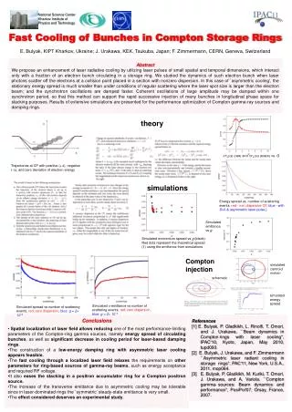
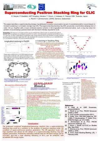
National Science CenterKharkov Institute of Physics and Technology Superconducting Positron Stacking Ring for CLIC E. Bulyak, P. Gladkikh, KIPT Kharkov, Ukraine; T. Omori, J. Urakawa, K. Yokoya, KEK, Tsukuba, Japan; L. Rinolfi, F. Zimmermann, CERN, Geneva, Switzerland Abstract This paper describes a superconducting storage ring dedicated to positron accumulation as part of a polarized positron source based on Compton scattering in a Compton storage ring (CR). The superconducting stacking ring (SR) can provide a synchrotron damping time of order 100 ms.Together with a novel combined injection scheme in the longitudinal and transverse plane, such a ring may solve the problem of accumulating a positron beam with the beam intensity required for CLIC. Introduction: Simulations of a Compton positron source indicate that a yield of a few 107 positrons per pulse is possible, with a longitudinal rmsemittance around 0.2–0.3 meV-s, and a transverse normalized rmsemittance of 8 × 10⁻³rad-m[3]. To obtain a high degree of polarization high-energy positrons have to be selected. An energy selection providing a beam polarization larger than 60% also decreases the transverse rmsemittance, by an estimated factor 2–4, and discards more than 70% of the produced positrons x-d stacking in Stacking Ring longitudinal stacking in PreDR Particle motion in the dispersion section is the superposition of the betatron oscillations and the displacement of the equilibrium orbit from the reference one X = Xb + Xs = X0*exp (-(N-1)/Tb)*cos (2p (N-1)Qb) + d0*h0*exp (-(N-1)/Ts)*cos (2p (N-1)Qs), whereTb, Tsare the damping times of the betatron and synchrotron oscillations (rated in turns); X0istheparticle displacement (betatron amplitude) from equilibrium orbit Xc = η0*d0;Qb, Qsare the numbers of the betatron and synchrotron oscillations per turn; N is turn number, d0 the momentum deviation, h0 the dispersion function at the injection azimuth Phase-space snapshots for CLIC-PDR stacking process: first bunchlet on first turn (left), and 60 bunches on turn 2400 (right) [5]. The blue line indicates the location of the septum blade, which changes after the injection turn due to a fast orbit bump. Resulting motion with synchrotron and betatron oscillations. Qb = n ± 1/4, Qs = 1/30, momentum deviation d0 = Dp/p0 = +3 %, dispersion at injection azimuth h0 = 1 m, particle displacement from equilibrium orbit X0 = 5 mm, synchrotron damping time Ts =>333 turns (100 μs for ring circumference C = 100 m) Injection simulation during 3 synchrotron cycles. Numbers near bunch position indicate turn number (0 labels injected bunch) Dynamic aperture at injection azimuth. IB: injected beam; EO: equilibrium orbit; SB: septum blade. Momentum deviation Dp/p0=3 %, dispersion at the injection azimuth h0=1 m. Stacking Ring layout. Energy E0=5 GeV, circumference C ≈ 125 m, bending field B = 6 T, energy losses DE ≈ 20 MeV / turn, synchrotron damping time ts= 104 ms (corresponds to 240 turns). IS1,IS2: injection septums; RF: rf-sections; PE: positron extraction. Simulation parameters & results: Injected particles number 100;transversal beam emittance 2000*10-6 m*rad (normalized); energy distribution is Gaussian Dp/p0=0.2 % > (20-15)/5000;septum thickness 0.5 mm;mom. deviation of injected beam from reference (pinj-po)/po=3%. Result: two particles are out of the dynamic aperture and are being lost during the injection;oneparticle of the injected bunch is being lost on septum at the beginning of the first turn;two particles are being lost on septum blade after the first turn;at a latter time particles are not being lost.Thus, 95 particles are successfully injected, i.e. the injection efficiency is equal to 95 %. Parameters of modified PreDR [5] and of proposed SR • Main parameters ofStacking Ring (SR) Time diagram of CLIC positron current. Single pulse consists of 312 positron bunches. Bunch-to-bunch spacing is 0.5 ns, bunch population Ne+ ~ 4*109, repetition rate is 50 Hz. • Injection turns number is limited by huge synchrotron radiation power. Target CLIC e+ current single bunch corresponds to SR beam current Istor ≈ 1.28 A. To get the fast damping we use SC SR with synchrotron energy loss ΔESR ≈ 19.8 MeV/turn. • For CLIC e+ current synchrotron radiation power would be PSR =0.5* Istor* ΔESR = 12.7 MW!!!Thus, we cannot stack the required positrons number during single stacking cycle. • Possibleoperation mode: • CR:circumference CCR ~ 300 m; #bunches NbCR = 250 (bunch spacing TbbCR = 4 ns); repetition rate frep=400 Hz (Trep=2.5 ms => 2500 turns = 500 turns (gamma generation) + 2000 turns (electron beam damping); • SR:Circumference CSR ~ 125 m; # bunches NbSR = 104 (bunch spacing TbbSR = 4 ns); • 1200 turns (positron injection to accumulate the target bunch population 4*107 e+) + 1200 turns (beam damping); • TDT: CTDT46.8m; #bunches NbTDT=39; (bunch spacing TbbTDT = 4 ns). • Time Diagram Transformer transforms pulse duration from ~420 ns in the SR to 156 ns in the damping ring DR. After 1200 damping turns positron beam is quickly extracted (3 turns in the TDT) from the SR to the TDT andto the pre-damping ring PDR from the TDT. Result is 39 bunches with target population on the PDR orbit. The above cycle repeated 8 times; every successive train of 39 positron bunches is shifted by 0.5 ns and during 8 cycles (20 ms) we obtain 312 bunches on the PDR orbit. This beam is injected to the DR and damps during 20 ms. This scheme reduces SR current by factor 8. Taking into account durations of beam accumulation and damping in the SR the average synchrotron radiation power is ~400 kW. References [1] S. Araki et al, 2005 Snowmass, physics/0509016. [2] L. Rinolfi et al, Proc. PAC09 Vancouver (2009) p. 2945. [3] A. Vivoli, private communication (2011). [4] P. Collier, Proc. PAC1995 Dallas pp. 551 (1995); P. Baudrenghien, P. Collier, Proc. EPAC'96 Sitges, pp. 415 (1996). [5] F. Zimmermann et al, Proc. PAC'09 Vancouver (2009) pp. 512. [6] T. Omori, L. Rinolfi, ILC-CLIC e+ Studies Mtg., May 2009. [7] F. Antoniou et al, Proc. PAC09 Vancouver (2009) p.~2760. [8] A. Vivoli, Pulse Stacking Meeting, LAL, 1 February 2008. Layout of the CLIC positron part. T:target; AMD: adiabatic matching device; PreAcc: injector to stacking ring; SR: stacking ring; TDT: time diagram transformer; PreDR, DR: damping rings; MainAcc: main linac • Conclusions • The proposed combined longitudinal-transverse injection into a superconducting stacking ring could be a solution to the problem of positron stacking under the condition of quasi-continuous positron generation. The CR operation mode with high repetition rate allows for the design of a superconducting stacking ring with realistic parameters. Preliminary estimates indicate that the SR beam energy can be 3.5-5,GeV, and that a high stacking efficiency of 95\% can be achieved, with acceptable SR energy losses.