Apache Energy Stag ESP Surface Equipment Overview
240 likes | 389 Views
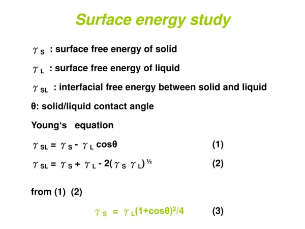
Apache Energy Stag ESP Surface Equipment Overview. 2011. ESP Surface Equipment - Purpose . Provides electrical power to downhole ESP system. Performs required power conversions which is fed to the ESP. Provides protection for downhole ESP system.

Apache Energy Stag ESP Surface Equipment Overview
E N D
Presentation Transcript
ESP Surface Equipment - Purpose • Provides electrical power to downhole ESP system. • Performs required power conversions which is fed to the ESP. • Provides protection for downhole ESP system. • Provides power for surface and downhole ESP instrumentation and data gathering equipment . • Data gathering point for surface and downhole ESP acquisition and control system. • Control operation of downhole ESP system.
ESP Surface Equipment - Components • Variable Speed Drive – control. • Step Up Transformers– power transformation. • Surface equipment for downhole sensor – data gathering, protection & control. • Remote Connection – data transmission • Junction Box with auxiliary equipments – PTs, Backspin Shut, Electrical Choke
Variable Speed Application – Low Voltage SCADA / Connectivity Interface VSD Power Module w/Controller Incoming 3-phase power Step-up transformer Junction Box Downhole ESP System Multisensor Surface Equipment
Variable Speed Drive - Basics • VSD – a device for taking a fixed frequency power supply and changing it to a variable frequency to drive the downhole equipment
Variable Speed Drive - Basics • New VSD features: • Incorporate Power Study Result • Built In Load Filter • Uniconn • Motor controller • Downhole gauge surface reader • Remote data transmission • Auxiliary equipment • Potential Transformers • Current Transformers • Backspin shunt
Step Up Transformer • Main purpose is to convert 3-phase power for ESP from a certain voltage to a different voltage level, as required by the application. • Therefore, main selection criteria is the required input and output voltages (tap setting).
Junction Box / Vent Box • Provides a connection point for the surface cable to downhole cable. • Allows for any gas to vent that may have migrated through to the power cable. • Provides easy accessible test point for electrically checking downhole equipment.
Junction Box / Auxiliary Box Auxiliary Junction Box for Stag, will be installed close to Step Up Transformer Phoenix electrical choke and fuses Potential Transformers (PT) Input Fuses for PTs Backspin Shunt CTs is located inside Step Up Transformer
Motor Controller • Uniconn • One platform of protection, monitoring, data gathering and interface between: • VSD and downhole ESP • Phoenix downhole gauge • Remote data monitoring • Auxiliary Inputs i.e.: PTs, CTs, digital input in Step Up Transformer, Platform Alarm (Process alarm and ESD)
Multisensor Surface Equipment • Surface Panel (PIC – Phoenix Interface Card) : • Provides power to power up downhole gauge • Data gathering/storing point • Provides protection (alarms/trips) for the VSD based on monitored parameters • 3-phase choke – decouple high voltage 3-phase electricity powering ESP from the surface panel • Apache Stag VSD is set up with Phoenix Sensor trip/alarms: • High Motor Temperature • PIC status/error
Remote Data Transmission • Remote monitoring of data gathered • Store and show the data from different sources • Uniconn is the interface with its modbus register • Remote control of ESP system • Remote start – stop (not for VSD trips) Apache Stag Troubleshooting Procedures has to be followed in any case of VSD trip due to active alarms.
Remote Data Transmission • Challenges: • Remotely gather the data • Analyze the gathered data • Make decisions based on the analysis on regular basis • Automate the analysis and decision-making processes
System analysis that can be done: Conceptual Design and Engineering Load Flow Studies Short-Circuit Studies Motor Starting Studies Transient Stability Studies Harmonic Studies and Mitigation Protective Equipment Coordination Equipment Evaluation Load Filter Analysis Power Studies
The 3 Main Safety Rules on VSDs • Installation • Operation • Maintenance & Starting-up Safety First!
Safety Hazardswith VSDs • Five primary hazards : • Electrical Shocks • Burns • Arc-Blast • Explosions • Fires • Danger signs for electrical hazards
The Three Main Mechanical & Environmental Installation Safety Precautions • Install in a secure and upright position in a well ventilated location. Ambient Temperature should be between -10° C and 50° C. • Ensure the ventilation is not blocked • Avoid installation in areas where high vibration, extreme heat, or sources of electrical noise are present.
The Three Main VSD Electrical Installation Safety Rules • Ground VSD, as per recommended instructions, to prevent electrical shock and reduce electrical noise. • Use lockout/tag out procedures before connecting 3 phases power to VSD. • Power conductors should be properly sized. In case of use of parallel power conductors to share load keep them in sets in each individual conduit.
The Main Safety Ruleson applying power to the unit • After Maintenance or when applying power for first time check: • That source power is connected to terminals L1, L2, L3 (R, S, T). Connection of incoming source power to any other terminals will damage the drive. • The 3-phase source power should be within the correct voltage and frequency tolerances. • The output leads must be connected to terminals T1, T2, T3 (U, V, W). • Make sure there are no short circuits or inadvertent grounds and tighten any loose connector terminal screw
VSD Output Power U (T-1), W(T-2), V(T-3) 3 Phases AC Input Power R (L-1),S (L-2),T (L-3)
The Three Main VSD Operation Safety Rules • Input voltage tolerance is +/- 10% of specified input voltage. Actual input frequency should be within +/- 3% of specified input frequency. • DO NOT TOUCH ANY INTERNAL PART WITH POWER APPLIED! • DO NOT OPERATE THE VSD WITH IT CABINET DOOR(S) OPEN!
The Three Main VSD MaintenanceSafety Rules • Use lockout/tag out procedures before performing any drive maintenance. • 2) A non-combustible insulating floor mat should be provided in the working area close the VSD under maintenance. • 3) Electronic boards are delicate and ESD sensitive, use protective equipment and follow ESD prevention procedures.