Download
1 / 52
600 likes | 1.08k Views
Chapter 12 Introduction to Networking and Local-Area Networks. 12-1: Network Fundamentals 12-2: LAN Hardware 12-3: Ethernet LANs 12-4: Token-Ring LAN. 12-1: Network Fundamentals 12-2: LAN Hardware 12-3: Ethernet LANs 12-4: Token-Ring LAN.

E N D
Chapter 12 Introduction to Networking and Local-Area Networks 12-1: Network Fundamentals 12-2: LAN Hardware 12-3: Ethernet LANs 12-4: Token-Ring LAN
12-1: Network Fundamentals 12-2: LAN Hardware 12-3: Ethernet LANs 12-4: Token-Ring LAN
A network is a communication system with two or more stations that can communicate with one another. The number of links L required between N PCs (nodes) is determined by using the formula L = N(N−1) / 2 Figure 12-1: A network of four PCs.
There are four basic Types of Networks • Wide-area networks (WANs), • Metropolitan-area networks (MANs) • Local-area networks (LANs) • Personal-area networks (PANs)
Wide-Area Networks (WANs) • A WAN covers a significant geographical area. • Public telephone systems are WANs. • There are also WANs that are not part of the public telephone networks, e.g., military. • The nationwide and worldwide fiber-optic networks to carry Internet traffic are also WANs. • Each telephone set is a node in a network that links local offices and central offices.
Metropolitan-Area Networks (MANs) • MANs are smaller than WANs and generally cover a city, town, or village. • MANs are usually fiber-optic rings encircling a city that provide local access to users. Businesses, governments, schools, hospitals, and others connect their internal LANs to them. • MANs also connect to local and long-distance telephone companies. The MANs provide fast and convenient connections to WANs for global Internet connectivity.
Local-Area Networks (LANs) • A LAN is the smallest type of network in general use. • A LAN consists primarily of personal computers interconnected within an office or building. • LANs can have as few as three to five users, although most systems connect to several thousand users. • Home networks of two or more PCs are also LANs and today most home LANs are fully wireless or incorporate wireless segments.
Network Topologies • The topology of a network describes the basic communication paths between, and methods used to connect, the nodes on a network. • The three most common topologies used in LANs are star, ring, and bus.
Star Topology • A basic star configuration consists of a central controller node and multiple individual stations connected to it. • The resulting system resembles a multipointed star. • The central or controlling PC, often referred to as the server, is typically larger and faster than the other PCs and contains a large hard drive where shared data and programs are stored.
Figure 12-3: A star LAN configuration with a server as the controlling computer.
Star Topology Characteristics • A star-type LAN is extremely simple and straightforward. • New nodes can be quickly and easily added to the system, and the failure of one node does not disable the entire system. • If the server node goes down, the network is disabled but individual PCs will continue to operate independently.
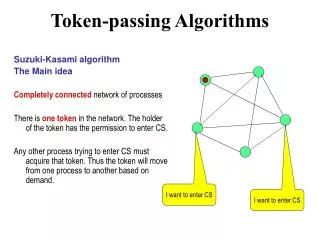
Ring Topology • In a ring configuration, the server or main control computer and all the computers are simply linked together in a single closed loop. • Usually, data is transferred around the ring in only one direction, passing through each node.
Ring Topology Characteristics • The ring topology is easily implemented and low in cost. • The downside of a ring network is that a failure in a single node generally causes the entire network to go down. • It is also difficult to diagnose problems on a ring.
Bus Topology • A bus is a common cable to which all of the nodes are attached. • The bus is bidirectional in that signals can be transmitted in either directions between any two nodes. • Only one node can transmit at a given time. • A signal to be transmitted can be destined for a single node, or transmitted or broadcast to all nodes simultaneously. • The bus is faster than other topologies, wiring is simple, and the bus can be easily expanded.
Mesh Topology • A mesh network is one in which each node is connected to all other nodes. • In a full mesh, every node can talk directly to any other node. • There are major costs and complications as the number of nodes increases, but the use of wireless interconnections between nodes helps to alleviate this problem.
Mesh Topology Characteristics • A variation of the full mesh is the partial mesh, in which all nodes can communicate with two or more other nodes. • The primary value of the mesh network is that there are multiple paths for data to take from one node to another. • This offers redundancy that can provide a continuous connection when one or more of the links are broken, thus providing increased network reliability.
12-1: Network Fundamentals 12-2: LAN Hardware 12-3: Ethernet LANs 12-4: Token-Ring LAN
All LANs are a combination of hardware and software. • The primary hardware devices are the computers, cables, and connectors. • Additional hardware includes: • Network interface cards (NICs) • Repeaters • Hubs and concentrators • Bridges • Routers • Gateways
Cables • Most LANs use some type of copper wire cable to carry data from one computer to another via baseband transmission. • The three basic cable types are: • Coaxial cable • Twisted pair • Fiber-optic cable
Coaxial Cable Characteristics • Its extremely wide bandwidth permits very high-speed bit rates. • Loss is generally high, but is usually offset by using repeaters that boost signal level. • The major benefit of coaxial cable is that it is completely shielded, so that external noise has little or no effect on it.
Figure 12-7 (a) Twisted-pair unshielded (UTP) cable. (b) Multiple shielded twisted-pair (STP) cable
Twisted Pair Characteristics • Twisted pair cable is two insulated copper wires twisted together loosely to form a cable. • Telephone companies use twisted pair to connect individual telephones to the central office. • The wire is solid copper, 22, 24, or 26 gauge. • The insulation is usually PVC. • Cheaper, lighter, and easier to work with than coaxial cables.
Fiber-Optic Cable Characteristics • Fiber-optic cableis a nonconducting cable consisting of a glass or plastic center cable surrounded by a plastic cladding encased in a plastic outer sheath. • Most fiber-optic cables are extremely thin glass, and many are usually bundled together. • Special fiber-optic connectors are required to attach them to the network equipment. • Speeds of up to 1 Tbps (terabits per second) are achievable by using fiber optics.
Figure 12-12 Modular (telephone) connectors used with twisted-pair cable. (a) RJ-11. (b) RJ-45
Optical Fiber Connectors http://www.tradevv.com/chinasuppliers/topfiber_p_62ed4/china-optical-fiber-connector.html
Network Interface Cards and Chips • A network interface card (NIC) provides the I/O interface between each node on a network and the network wiring. • NICs usually plug into the PC bus or are built into the PC motherboard and provide connectors at the rear of the computer for attaching the cable connectors. • The NIC is the key hardware component in any LAN. • The NIC completely defines the protocols and performance characteristics of the LAN.
Repeater • A repeater is an electronic circuit that takes a partially degraded signal, boosts its level, shapes it up, and sends it on its way. • Repeaters are small, inexpensive devices that can be inserted into a line with appropriate connectors or built into other LAN equipment. • Most repeaters are really transceivers, bidirectional circuits that can both send and receive data. Figure 12-14: Concept of a repeater
Hub • A hub is a central connecting box designed to receive the cable inputs from the various PC nodes and to connect them to the server. • In most cases, hub wiring physically resembles a star because all cabling comes into a central point, or hub. • Hubs are usually active devices containing repeaters. They amplify and reshape the signal and transmit it to all connection parts.
Switch • A switch is a hublike device that is used to connect individual PC nodes to the network wiring. • A hub shares the total bandwidth among all users, while a switch provides a dedicated line at full bandwidth between every two devices transmitting to each other. • Switches have largely replaced hubs in most large LANs because they greatly expand the number of possible nodes and improve performance.
Bridge • A bridge is a network device that is connected as a node on a network and performs bidirectional communication between two LANs. • A bridge is generally designed to interconnect two LANs with the same protocol, for example, two Ethernet networks, although some perform protocol conversion. • Remote bridges are special bridges used to connect two LANs that are separated by a long distance.
Router • Routers are designed to connect two networks. • The main difference between bridges and routers is that routers are intelligent devices that have decision-making and switching capabilities. • The basic function of a router is to expedite traffic flow on both networks and maintain maximum performance. • Some routers are a combination of a bridge and a router.
Gateway • A gateway is another internetwork device that acts as an interface between two LANs or between a LAN and a larger computer system. • The primary benefit of a gateway is that it can connect networks with incompatible protocols and configurations. • The gateway acts as a two-way translator that allows systems of different types to communicate. • Most gateways are computers and are sometimes referred to as gateway servers.
Figure 12-17: A gateway commonly connects a LAN to a larger host computer Internet Service Provider
12-1: Network Fundamentals 12-2: LAN Hardware 12-3: Ethernet LANs 12-4: Token-Ring LAN
Ethernet • One of the oldest and by far the most widely used of all LANs is Ethernet. • The original versions of Ethernet used a bus topology. Today, most use a physical star configuration. • Ethernet uses baseband data-transmission methods. • The serial data to be transmitted is placed directly on the bus media. • Before transmission, the binary data is encoded into a unique variation of binary code known as the Manchester code.
Ethernet Speed • The standard transmission speed for Ethernet LANs is 10 Mbps. • The most widely used version of Ethernet is called Fast Ethernet.It has a speed of 100 Mbps. • Other versions of Ethernet run at speeds of 1 Gbpsor 100 Gbps, typically over fiber-optic cable but also on shorter lengths of coaxial or twisted-pair cable.
Transmission Medium: Coaxial Cable • The original transmission medium for Ethernet was coaxial cable. However, today twisted-pair versions of Ethernet are more popular. • Ethernet systems using thick coaxial cable are generally referred to as 10Base-5 systems: • 10 means a 10-Mbps speed • Base means baseband operation • 5 designates a 500-m maximum distance between nodes, transceivers, or repeaters. • Ethernet LANs using thick cable are also referred to as Thicknet.
Transmission Medium: Coaxial Cable • Ethernet systems implemented with thinner coaxial cable are known as 10Base-2, or Thinnetsystems. • The 2indicates the maximum 200-m (actually, 185-m) run between nodes or repeaters. • The most widely used thin cable is RG-58/U. • It is much more flexible and easier to work with than RG-8/U cable.
Transmission Medium: Twisted-Pair Cable • More recent versions of Ethernet use twisted-pair cable. • The twisted-pair version of Ethernet is referred to as a 10Base-T network, where the Tstands for twisted-pair.
Transmission Medium:100-Mbps Ethernet • By far the most popular version of 100-Mbps Ethernet is 100Base-TX, or Fast Ethernet. • It uses two unshielded twisted pairs instead of the single pair used in standard 10Base-T. • One pair is used for transmitting, and the other is used for receiving, permitting full duplex operation, which is not possible with standard Ethernet.
Transmission Medium: Gigabit Ethernet • Gigabit Ethernet(1 GE) is capable of achieving 1000 Mbps or 1 Gbps over fiber-optic cable.
Transmission Medium: 10-Gbit Ethernet • The newest version of Ethernet is 10-Gbit Ethernet(10 GE), which permits data speeds up to 10 Gbps over fiber-optic cable. • Three of the five variations of 10-Gbit Ethernet use serial data transmission. • The other two use what is called wide-wavelength division multiplexing (WWDM).Also known as coarse wavelength division multiplexing (CWDM),these versions divide the data into four channels and transmit it simultaneously over four different wavelengths of infrared light near 1310 nm. • WWDM is similar to frequency-division multiplexing.
Access Method • Access methodrefers to the protocol used for transmitting and receiving information on a bus. • Ethernet uses an access method known as carrier sense multiple access with collision detection (CSMA/CD) • Occasionally, two or more nodes may attempt to transmit at the same time. When this happens, a collisionoccurs and both transmitting stations will terminate transmission. • The CSMA/CD algorithm calls for the sending stations to transmit again after a brief pause.