Download
1 / 100
1.06k likes | 1.39k Views
Fundamentals of Hardware Description Language. Lecturer: Yu-Hao Chen( 陳郁豪 ) Date: 2011.03.02. Based on: Ch.1-3 of the textbook Review: Logic Design (Concepts of Propagation Delay). Outline. Overview and History Hierarchical Design Methodology Levels of Modeling Behavioral Level Modeling

E N D
Fundamentals of Hardware Description Language Lecturer: Yu-Hao Chen(陳郁豪) Date: 2011.03.02 Based on: Ch.1-3 of the textbook Review: Logic Design (Concepts of Propagation Delay)
Outline • Overview and History • Hierarchical Design Methodology • Levels of Modeling • Behavioral Level Modeling • Register Transfer Level (RTL) Modeling • Structural/Gate Level Modeling • Language Elements • Logic Gates • Data Type • Timing and Delay • Simulation & Verification Yu-Hao
Hardware Description Language (1/2) From Wikipedia • Hardware Description Language (HDL) is any language from a class of computer languages and/or programming languages for formal description of electronic circuits, and more specifically, digital logic. • HDL can • describe the circuit's operation, design, organization • verify its operation by means of simulation. • Now HDLs usually merge Hardware Verification Language, which is used to verify the described circuits. Yu-Hao
Hardware Description Language (2/2) Yu-Hao • HDLs are used to write executable specifications of some piece of hardware. • Designed to implement the semantics of the language statements with native supporting to simulate the progress of time • Being executable • Provides the hardware designer the ability to model a piece of hardware before it is created physically. • Supporting discrete-event (digital) or continuous-time (analog) modeling, e.g.: • SPICE, Verilog HDL, VHDL, SystemC
High-Level Programming Language It’s possible to describe a hardware (operation, structure, timing, and testing methods) in C/C++/Java, why do we use HDL? The efficiency (to model/verify) does matter. Native support to concurrency Native support to the simulation of the progress of time Native support to different model of signal states The required level of detail determines the language we use. Yu-Hao
List of HDL for Digital Circuits • PALASM (for Programmable Array Logic (PAL) devices) • Ruby (hardware description language) • RHDL (based on the Ruby programming language) SDL based on Tcl. • CoWareC, a C-based HDL by CoWare. Now discontinued in favor of SystemC • SystemVerilog, a superset of Verilog, with enhancements to address system-level design and verification • SystemC, a standardized class of C++ libraries for high-level behavioral and transaction modeling of digital hardware at a high level of abstraction, i.e. system-level • SystemTCL, SDL based on Tcl. Verilog VHDL Advanced Boolean Expression Language (ABEL) AHDL (Altera HDL, a proprietary language from Altera) Atom (behavioral synthesis and high-level HDL based on Haskell) Bluespec (high-level HDL originally based on Haskell, now with a SystemVerilog syntax) Confluence (a functional HDL; has been discontinued) CUPL (a proprietary language from Logical Devices, Inc.) Handel-C (a C-like design language) C-to-Verilog (Converts C to Verilog) HDCaml (based on Objective Caml) Hardware Join Java (based on Join Java) HML (based on SML) Hydra (based on Haskell) Impulse C (another C-like language) JHDL (based on Java)Lava (based on Haskell) Lola (a simple language used for teaching) MyHDL (based on Python) Yu-Hao
About Verilog • Introduction on 1984 by Phillip Moorby and Prabhu Goel in Automated Integrated Design System (renamed to Gateway Design Automation and bought by Cadence Design Systems) • Open and Standardize (IEEE 1364-1995) on 1995 by Cadence because of the increasing success of VHDL (standard in 1987) • Become popular and makes tremendous improvement on productivity • Syntax similar to C programming language, though the design philosophy differs greatly Yu-Hao
History/Branch of Verilog Verilog IEEE Std 1364-1995 Verilog-2001 IEEE Std 1364-2001 Verilog-2005 IEEE Std 1364-2005 SystemVerilog IEEE Std 1800-2005 Digital-signal HDL Yu-Hao
Outline • Overview and History • Hierarchical Design Methodology • Levels of Modeling • Behavioral Level Modeling • Register Transfer Level (RTL) Modeling • Structural/Gate Level Modeling • Language Elements • Logic Gates • Data Type • Timing and Delay • Simulation & Verification Yu-Hao
Hierarchical Modeling Concept • Introduce top-down and bottom-up design methodologies • Introduce module concept and encapsulation for hierarchical modeling • Explain differences between modules and module instances in Verilog Yu-Hao
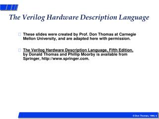
Top-down Design Methodology • We define the top-level block and identify the sub-blocks necessary to build the top-level block. • We further subdivide the sub-blocks until we come to leaf cells, which are the cells that cannot further be divided. Top level block sub block 1 sub block 2 sub block 3 sub block 4 leaf cell leaf cell leaf cell leaf cell leaf cell leaf cell leaf cell leaf cell Yu-Hao
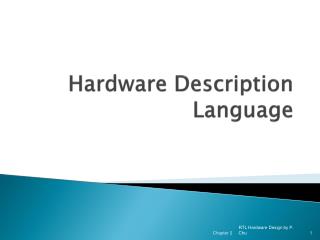
Bottom-up Design Methodology • We first identify the building block that are available to us. • We build bigger cells, using these building blocks. • These cells are then used for higher-level blocks until we build the top-level block in the design. Top level block macro cell 1 macro cell 2 macro cell 3 macro cell 4 leaf cell leaf cell leaf cell leaf cell leaf cell leaf cell leaf cell leaf cell Yu-Hao
Example: 16-bit Adder Yu-Hao
Hierarchical Modeling in Verilog • A Verilog design consists of a hierarchy of modules. • Modules encapsulate design hierarchy, and communicate with other modules through a set of declared input, output, and bidirectional ports. • Internally, a module can contain any combination of the following • net/variable declarations (wire, reg, integer, etc.) • concurrent and sequential statement blocks • instances of other modules (sub-hierarchies). Yu-Hao
Design Encapsulation • Encapsulate structural and functional details in a module • Encapsulation makes the model available for instantiation in other modules module <Module Name> (<PortName List>); // Structural part <List of Ports> <Lists of Nets and Registers> <SubModule List> <SubModule Connections> // Behavior part <Timing Control Statements> <Parameter/Value Assignments> <Stimuli> <System Task> endmodule Yu-Hao
Module • Basic building block in Verilog. • Module • Created by “declaration” (can’tbe nested) • Used by “instantiation“ • Interface is defined by ports • May contain instances of other modules • All modules run concurrently Yu-Hao
Instances • A module provides a template from which you can create actual objects. • When a module is invoked, Verilog creates a unique object from the template. • Each object has its own name, variables, parameters and I/O interface. Yu-Hao
Module Instantiation instance example Yu-Hao
Analogy: module ↔ class As module is to Verilog HDL, so class is to C++programming language. Yu-Hao
Analogy: module ↔ class • assign and evaluate() is simulated/called at each Ti+1 = Ti + tresolution Model AND gate with C++ Model AND gate with Verilog HDL Yu-Hao
Outline • Overview and History • Hierarchical Design Methodology • Levels of Modeling • Behavioral Level Modeling • Register Transfer Level (RTL) Modeling • Structural/Gate Level Modeling • Language Elements • Logic Gates • Data Type • Timing and Delay • Simulation & Verification Yu-Hao
Cell-Based Design and Levels of Modeling Most used modeling level, easy for designer, can be simulated and synthesized to gate-level by EDA tools Behavioral Level Common used modeling level for small sub-modules, can be simulated and synthesized to gate-level Register Transfer Level (RTL) Usually generated by synthesis tool by using a front-end cell library, can be simulated by EDA tools. A gate is mapped to a cell in library Structural/Gate Level Transistor/Physical Level Usually generated by synthesis tool by using a back-end cell library, can be simulated by SPICE Yu-Hao
Tradeoffs Among Modeling Levels Each level of modeling permits modeling at a higher or lower level of detail. More detail means more efforts for designers and the simulator. Always keep in mind which level of modeling is adopted Yu-Hao
An Example1-bit Multiplexer To “select” output out = (sel’ & in1) + (sel & in2) Yu-Hao
in1 a1 a1_o out iv_sel o1 in2 a2 a2_o n1 sel iv_sel Gate Level Description Gate Level:you see only netlist (gates and wires) in the code Yu-Hao
Behavioral Level/RTL Description assign always block RTL:describe logic/arithmetic function between input node and output node Behavior: RTL in an event-driven behavior description construct Yu-Hao
Outline • Overview and History • Hierarchical Design Methodology • Levels of Modeling • Behavioral Level Modeling • Register Transfer Level (RTL) Modeling • Structural/Gate Level Modeling • Language Elements • Logic Gates • Data Type • Timing and Delay • Simulation & Verification Yu-Hao
Verilog Language Rules • Verilog is a case sensitive language (with a few exceptions) • Identifiers (space-free sequence of symbols) • upper and lower case letters from the alphabet • digits (0, 1, ..., 9) • underscore ( _ ) • $ symbol (for system tasks) • Max length of 1024 symbols • Terminate lines with semicolon; • Single line comments: • // A single-line comment goes here • Multi-line comments: • /* Do not /* nest multi-line comments*/ like this */ Yu-Hao
Verilog Basis Cell • Verilog Basis Components • parameter declarations • nets or reg declarations • port declarations • Continuous assignments • Module instantiations • Gate instantiations • Function definitions • always blocks • task statements Yu-Hao
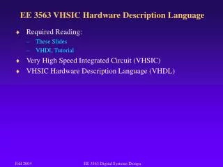
module input output reg or net net reg or net net inout net net Port Declaration • Three port types • Input port • input a; • Output port • output b; • Bi-direction port • inout c; Yu-Hao
Data Types • nets are further divided into several net types • wire, wand, wor, tri, triand, trior, supply0, supply1 • registers – variable to store a logic value for event-driven simulation - reg • integer - supports computation 32-bits signed • time - stores time 64-bit unsigned • real - stores values as real numbers • realtime - stores time values as real numbers Yu-Hao
Net Types • The most common and important net types • wire and tri • for standard interconnection wires • supply 1 and supply 0 • Other wire types • wand, wor, triand, and trior • for multiple drivers that are wired-anded and wired-ored • tri0 and tri1 • pull down and pull up • trireg • for net with capacitive storage • If all drivers at z, previous value is retained Yu-Hao
Register Types • reg • any size, unsigned • integer (not synthesizable) • integet a,b; // declaration • 32-bit signed (2’s complement) • time (not synthesizable) • 64-bit unsigned, behaves like a 64-bit reg • $display(“At %t, value=%d”,$time,val_now) • real, realtime (not synthesizable) • real c,d; //declaration • 64-bit real number • Defaults to an initial value of 0 Yu-Hao
Integer, Real, & Time • Data types not for hardware description • For simulation control, data, timing extraction. • integer counter; • initial counter = -1; • real delta; • initial delta = 4e10; • time sim_time; • initial sim_time = $time; Yu-Hao
Wire & Reg • wire(wand, wor, tri) • Physical wires in a circuit • Cannot assign a value to a wire within a function or a begin…..end block • A wire does not store its value, it must be driven by • by connecting the wire to the output of a gate or module • by assigning a value to the wire in a continuous assignment • An un-driven wire defaults to a value of Z (high impedance). • Input, output, inout port declaration -- wire data type (default) Yu-Hao
Wire & Reg • reg • A event driven variable in Verilog • Use of “reg” data type is not exactly stands for a really DFF. • Use of wire & reg • When use “wire” usually use “assign” and “assign” does not appear in “always” block • When use “reg” only use “a=b” , always appear in “always” block module test(a,b,c,d); input a,b; output c,d; reg d; assign c=a; always @(b) d=b; endmodule Yu-Hao
Nets-Wired Logic • The family of nets includes the types wand and wor • A wand net type resolves multiple driver as wired-and logic, e.g. open collector technology • A wor net type resolves multiple drivers as wired-or logic, e.g. emitter-coupled technology • The family of nets includes supply0 and supply1 • supply0 has a fixed logic value of 0 to model a ground connection • supply1 has a fixed logic value of 1 to model a power connection • Used when model at transistor-level Yu-Hao
More about Nets:Tri tri: a data type identified distinctively to indicate that it will be thi-state (Z) in hardware, same functionality as wire triand and trior:similar as wand and wor tri0: resistive pull-down tri1: resistive pull-up trireg: a net models the charge stored on a physical net Used when model at transistor-level Yu-Hao
Data Type - Examples reg a; // scalar register wand b; // scalar net of type “wand” reg [3:0] c; // 4-bit register tri [7:0] bus; // tri-state 8-bit bus reg [1:4] d; // 4-bit trireg (small) store; // specify logical strength (rare used) wire/tri truth table wand/triand wor/trior Yu-Hao
Vector • wire and reg can be defined vector, default is 1bit • vector is multi-bits element • Format: [High#:Low#] or [Low#:High#] • Using range specify part signals wire a; // scalar net variable, default wire [7:0] bus; // 8-bit bus reg clock; // scalar register, default reg [0:23] addr; // Vector register, virtual address 24 bits wide bus[7] // bit #7 of vector bus bus[2:0] // Three least significant bits of vector bus // using bus[0:2] is illegal because the significant bit should // always be on the left of a range specification addr[0:1] // Two most significant bits of vector addr Yu-Hao
Array • Arrays are allowed in Verilog for reg, integer, time, and vector register data types. • Multidimensional array are not permitted in Verilog. integer count[0:7]; // An array of 8 count variables reg bool[31:0]; // Array of 32 one-bit Boolean register variables time chk_ptr[1:100]; // Array of 100 time checkpoint variables reg [4:0] port_id[0:7]; // Array of 8 port_id, each port_id is 5 bits wide integer matrix[4:0][4:0] // Illegal declaration count[5] // 5th element of array of count variables chk_ptr[100] // 100th time check point value port_id[3] // 3rd element of port_id array. This is a 5-bit value Yu-Hao
Memories • In digital simulation, one often needs to model register files, RAMs, and ROMs. • Memories are modeled in Verilog simply as an array of registers. • Each element of the array is known as a word, each word can be one or more bits. • It is important to differentiate between • n 1-bit registers • One n-bit register reg mem1bit[0:1023]; // Memory mem1bit with 1K 1-bit words reg [7:0] mem1byte[0:1023]; // Memory mem1byte with 1K 8-bit words mem1bit[255] // Fetches 1 bit word whose address is 255 Mem1byte[511] // Fetches 1 byte word whose address is 511 Yu-Hao
Arrays Extended after Verilog-2001 //bit reg r_1bit; //vector reg [3:0] r_4bit_vec; //1D array: memory: 32bit×8 reg [31:0] r_memory [7:0]; //1D array: 8bit×8 wire [7:0] w_net [7:0]; //2D array: 4bit×8×8 trireg [3:0] row_col_addr [0:7][0:7]; //3D array:100×16×4float variables real float_array [0:99][1:16][10:13]; In Verilog-1995, only reg, integer, and time can be declared as array. Array is limited to 1D. In Verilog-2001, arrays of real, realtime, and any type of net are allowed. Yu-Hao
Strings • String: a sequence of 8-bits ASCII values • Special characters \n newline \t tab character \\ \ character \” “ character %% % character \abc ASCII code module string; reg [8*14:1] strvar; initial begin strvar = “Hello World”; // stored as 000000486561…726c64 strvar = “Hello World!!”; // stored as 00486561…726c642121 end endmodule Yu-Hao
Four-Valued Logic • Verilog’s nets and registers hold four-valued data • 0 represent a logic zero or false condition • 1 represent a logic one or true condition • z • Output of an undriven tri-state driver –high-impedance value • Models case where nothing is setting a wire’s value • x • Models when the simulator can’t decide the value – uninitialized or unknown logic value • Initial state of registers • When a wire is being driven to 0 and 1 simultaneously • Output of a gate with z inputs Yu-Hao
0 1 X Z 0 0 0 0 0 1 0 1 X X X 0 X X X Z 0 X X X Logic System in Verilog • Four values: 0, 1, x or X, z or Z // Not case sensitive here • The logic value x denotes an unknown (ambiguous) value • The logic value z denotes a high impedance • Primitives have built-in logic • Simulators describe 4-value logic (see Appendix A in text) Yu-Hao
Resolution of Contention Between Drivers • The value on a wire with multiple drivers in contention may be x Yu-Hao
Logic Strength Levels • Types of strengths • Charge strength: trireg (large>medium>small) • Drive strength: <Net> (supply>strong>pull>weak) • Syntax • Strength level <NetType> <Strength> <Range> <Delay> <Variables>; trireg (large) [1:4] #5 c1; weakest strongest highz small medium weak large pull strong supply Yu-Hao
Number Representation • Format: <size>’<base_format><number> • <size> - decimal specification of number of bits • default is unsized and machine-dependent but at least 32 bits • <base format> - ' followed by arithmetic base of number • <d> <D> - decimal - default base if no <base_format> given • <h> <H> - hexadecimal • <o> <O> - octal • <b> <B> - binary • <number> - value given in base of <base_format> • _ can be used for reading clarity • If first character of sized, binary number 0, 1, x or z, will extend 0, 1, x or z (defined later!) Yu-Hao
Number Representation • Examples: • 6’b010_111 gives 010111 • 8’b0110 gives 00000110 • 4’bx01 gives xx01 • 16’H3AB gives 0000001110101011 • 24 gives 0…0011000 • 5’O36 gives 11100 • 16’Hx gives xxxxxxxxxxxxxxxx • 8’hz gives zzzzzzzz Yu-Hao