Serial Peripheral Interface (SPI) Bus
Serial Peripheral Interface (SPI) Bus. SPI Bus. There is no official specification for the SPI bus. It is necessary to consult the data sheets of the devices. Use to connect integrated circuits on a circuit board.

Serial Peripheral Interface (SPI) Bus
E N D
Presentation Transcript
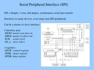
SPI Bus There is no official specification for the SPI bus. It is necessary to consult the data sheets of the devices. Use to connect integrated circuits on a circuit board. Important parameters are the permitted clock frequencies and the type of valid transitions. Master - Slave (1 or more slaves) configuration. The master is usually a microprocessor.
SPI Bus • SPI keeps the number of signal connections to a minimum and so reduces circuit board complexity. • Many different peripheral device types available. • Many different manufacturers of SPI devices (originally Motorola) - multiple sources • Not all manufacturers products are directly compatible! - small variations but can usually be worked around. • Typical SPI devices are :- • Flash EEPROM, ADC, DAC, temperature sensor, digital IO,RTC digital potentiometer etc.
SPI signals • The SPI bus specifies four logic signals. • SCLK - Serial Clock (output from master) • MOSI - Master Output, Slave Input (output from master) • MISO - Master Input, Slave Output (output from slave) • SS - Slave Select (active low; output from master) • Alternative naming conventions • SCK, CLK - Serial Clock (output from master) • SDI, DI, SI - Serial Data In • SDO, DO, SO - Serial Data Out • SSEL - Slave Select
Typical SPI Configuration The master pulls the slave select low and then issues clock cycles. The clock frequency is not specified in the SPI protocol and can be anything from 0 up to 70MHz depending on the characteristics of the slave device. The data transfer then takes place. The master then de-selects the slave.
Simple master slave implementation • During each SPI clock cycle, a full duplex data transmission occurs: • the master sends a bit on the MOSI line; the slave reads it from that same line • the slave sends a bit on the MISO line; the master reads it from that same line • Not all transmissions require all four of these operations to be meaningful but they do happen. • The number of bits transferred is not fixed but is usually a multiple of 8-bits.
Basic serial data transfer MASTER SLAVE MOSI SCLK SS MISO The registers within the master and slave act like shift registers shifting one bit on every cycle of the SCLK. 6-7
Data transfer details Most SPI interfaces have two configuration bits, called clock polarity (CPOL) and clock phase (CPHA). CPOL determines whether the shift clock's idle state is low (CPOL=0) or high (CPOL=1). CPHA determines on which clock edges data is shifted in and out (for CPHA=0, MOSI data is shifted out on falling edge, MISO data is shifted in on rising edge). As each bit has two states, this allows for four different combinations, all of which are incompatible with each other. For two SPI devices to talk to each other, they need to be set to use the same clock polarity and phase settings.
SPI Data Transfer Modes • These four modes are the combinations of CPOL and CPHA. • Modes 0 and 3 are the most common. • With SPI modes 0 and 3, data is always latched in on the rising edge of SCK and always output on the falling edge of SCK.
Multiple Slaves • If multiple slave devices exist, the master normally generates a separate slave select signal for each slave. - Star connection. SS Alternative daisy chain connection -requires only one slave select signal
SPI Bus characteristics It is up to the master and slave devices to know whether a received byte is meaningful or not. So a device must discard the received byte in a "transmit only" frame or generate a dummy byte for a "receive only" frame. No Acknowledgement Master doesn't even know if slave is present! Slaves can be thought of as IO devices of the master.
/*Initialise SSP in SPI mode */ void init_SSP1(void) { IODIR0 = IODIR0|PIN_SSP1_SS; //Enable SSEL pin as GPIO PINSEL0 |= 0x000A8000; //Enable SSP1 pins wih SSEL as GPIO //PINSEL0 |= 0x000AA000; //Enable SSP1 pins wiht SSEL as SS /* Set DSS data to 8-bit, Frame format SPI, CPOL = 0, CPHA = 0, and SCR (serial clock Rate (presscaler) is 15 */ SSP1CR0 = 0xFF07; SSP1CR1 = 0x00000002; //Configure as SPI Master /* SSPCPSR clock prescale register, master mode, minimum divisor is 0x02 MAX 254 */ SSP1CPSR = 15; }
` /*Send data to the SSP the start address and number of bytes (size of array) must be given*/ void SSP1SendData(unsigned char *data_add,unsigned char arr_size) { int i; SSP1_SS(0); //Select slave active low for(i=0;i<arr_size;i++) { while ( (SSP1SR & SSPSR_BSY) ); /* Wait until the Busy bit is cleared */ SSP1DR = *data_add; while ((SSP1SR & SSPSR_BSY) ); /* Wait until the Busy bit is cleared */ data_add++; } SSP1_SS(1); //de-select slave }
/*Receive data to the SSP the start address of where the data should be stored, size of the data must be given */ void SSP1ReceiveData(unsigned char *data_add,unsigned char arr_size) { int i; SSP1_SS(0); for(i=0;i<arr_size;i++) { SSP1DR = 0x00; //dummy write while ( (SSP1SR & SSPSR_BSY) ); /* Wait until the Busy bit is cleared */ *data_add= SSP1DR; while ((SSP1SR & SSPSR_BSY) ); /* Wait until the Busy bit is cleared */ data_add++; } SSP1_SS(1); }
Example SPI devices 25LC020A - 2K SPI Bus Serial EEPROM TC77-5.0 - Thermal Sensor with SPI Interface MCP3201 - 2.7V 12-Bit A/D Converter with SPI Serial Interface MCP4822 - 12-Bit DAC with Internal VREF and SPI Interface MCP41010 - Single/Dual Digital Potentiometer with SPI Interface MCP6S92 - Single-Ended, Rail-to-Rail I/O, Low-Gain PGA MCP23S08 - 8-Bit I/O Expander with Serial Interface The PICkit™ Serial SPI Demo Board was designed to easily
Place jumper on the required device Note: On the demo boards the CS is global. You must manually use the jumper to select the device you wish to use!