Download
1 / 37
370 likes | 519 Views
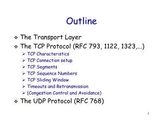
full duplex data: bi-directional data flow in same connection MSS: maximum segment size(512 to 1500 app data) connection-oriented: handshaking (exchange of control msgs) init’s sender, receiver state before data exchange flow controlled: sender will not overwhelm receiver. point-to-point:

E N D
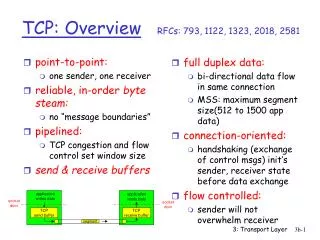
full duplex data: bi-directional data flow in same connection MSS: maximum segment size(512 to 1500 app data) connection-oriented: handshaking (exchange of control msgs) init’s sender, receiver state before data exchange flow controlled: sender will not overwhelm receiver point-to-point: one sender, one receiver reliable, in-order byte steam: no “message boundaries” pipelined: TCP congestion and flow control set window size send & receive buffers TCP: OverviewRFCs: 793, 1122, 1323, 2018, 2581 3: Transport Layer
32 bits source port # dest port # sequence number acknowledgement number head len not used rcvr window size U A P R S F checksum ptr urgent data Options (variable length) application data (variable length) TCP segment structure URG: urgent data (generally not used) counting by bytes of data (not segments!) ACK: ACK # valid PSH: push data now (generally not used) # bytes rcvr willing to accept RST, SYN, FIN: connection estab (setup, teardown commands) Internet checksum (as in UDP) 3: Transport Layer
TCP Header Fields • Options generally not there so 20-byte header is common • rcvr window size is used for FLOW CONTROL by the receiver • RST, SYN and FIN: connection mgmt • PSH: Data is to be pushed to upper layer immediately (NOT USED) • URG and ptr to urgent data fields are also not used commonly 3: Transport Layer
Seq. #’s: byte stream “number” of first byte in segment’s data ACKs: seq # of next byte expected from other side cumulative ACK Q: how receiver handles out-of-order segments A: TCP spec doesn’t say, - up to implementor time TCP seq. #’s and ACKs Host B Host A User types ‘C’ Seq=42, ACK=79, data = ‘C’ host ACKs receipt of ‘C’, echoes back ‘C’ Seq=79, ACK=43, data = ‘C’ host ACKs receipt of echoed ‘C’ Seq=43, ACK=80 simple telnet scenario 3: Transport Layer
TCP: reliable data transfer event: data received from application above simplified sender, assuming • one way data transfer • no flow, congestion control create, send segment wait for event event: timer timeout for segment with seq # y wait for event retransmit segment event: ACK received, with ACK # y ACK processing 3: Transport Layer
TCP: reliable data transfer 00sendbase = initial_sequence number 01 nextseqnum = initial_sequence number 02 03 loop (forever) { 04 switch(event) 05 event: data received from application above 06 create TCP segment with sequence number nextseqnum 07 start timer for segment nextseqnum 08 pass segment to IP 09 nextseqnum = nextseqnum + length(data) 10 event: timer timeout for segment with sequence number y 11 retransmit segment with sequence number y 12 compue new timeout interval for segment y 13 restart timer for sequence number y 14 event: ACK received, with ACK field value of y 15 if (y > sendbase) { /* cumulative ACK of all data up to y */ 16 cancel all timers for segments with sequence numbers < y 17 sendbase = y 18 } 19 else { /* a duplicate ACK for already ACKed segment */ 20 increment number of duplicate ACKs received for y 21 if (number of duplicate ACKS received for y == 3) { 22 /* TCP fast retransmit */ 23 resend segment with sequence number y 24 restart timer for segment y 25 } 26 } /* end of loop forever */ Simplified TCP sender 3: Transport Layer
TCP ACK generation[RFC 1122, RFC 2581] TCP Receiver action delayed ACK. Wait up to 500ms for next segment. If no next segment, send ACK immediately send single cumulative ACK send duplicate ACK, indicating seq. # of next expected byte immediate ACK if segment starts at lower end of gap Event in-order segment arrival, no gaps, everything else already ACKed in-order segment arrival, no gaps, one delayed ACK pending out-of-order segment arrival higher-than-expect seq. # gap detected arrival of segment that partially or completely fills gap 3: Transport Layer
Host A Host B Seq=92, 8 bytes data ACK=100 timeout X loss Seq=92, 8 bytes data ACK=100 time time lost ACK scenario TCP: retransmission scenarios Host A Host B Seq=92, 8 bytes data Seq=100, 20 bytes data Seq=92 timeout ACK=100 ACK=120 Seq=100 timeout Seq=92, 8 bytes data ACK=120 premature timeout, cumulative ACKs 3: Transport Layer
receiver: explicitly informs sender of (dynamically changing) amount of free buffer space RcvWindow field in TCP segment sender: keeps the amount of transmitted, unACKed data less than most recently received RcvWindow flow control TCP Flow Control sender won’t overrun receiver’s buffers by transmitting too much, too fast RcvBuffer= size of TCP Receive Buffer RcvWindow = amount of spare room in Buffer receiver buffering 3: Transport Layer
TCP Flow Control • At Receiver: • LastByteRcvd and LastByteRead pointers • LastByteRcvd – LastByteRead <=RcvBuffer • RcvWindow = RcvBuffer – [LastByteRcvd – LastByteRead] • At Sender: • LastByteSent – LastByteAcked <= RcvWindow • What if receiver advertises RcvWindow of size 0 and it has nothing to send later to the sender? • How will the sender know if the RcvWindow size grows? 3: Transport Layer
Q: how to set TCP timeout value? longer than RTT note: RTT will vary too short: premature timeout unnecessary retransmissions too long: slow reaction to segment loss Q: how to estimate RTT? SampleRTT: measured time from segment transmission until ACK receipt ignore retransmissions, cumulatively ACKed segments SampleRTT will vary, want estimated RTT “smoother” use several recent measurements, not just current SampleRTT TCP Round Trip Time and Timeout 3: Transport Layer
Setting the timeout EstimtedRTT plus “safety margin” large variation in EstimatedRTT -> larger safety margin TCP Round Trip Time and Timeout EstimatedRTT = (1-x)*EstimatedRTT + x*SampleRTT • Exponential weighted moving average • influence of given sample decreases exponentially fast • typical value of x: 0.125 Timeout = EstimatedRTT + 4*Deviation Deviation = (1-x)*Deviation + x*|SampleRTT-EstimatedRTT| 3: Transport Layer
Recall:TCP sender, receiver establish “connection” before exchanging data segments initialize TCP variables: seq. #s buffers, flow control info (e.g. RcvWindow) client: connection initiator Socket clientSocket = new Socket("hostname","port number"); server: contacted by client Socket connectionSocket = welcomeSocket.accept(); Three way handshake: Step 1:client end system sends TCP SYN control segment to server specifies initial seq # Step 2:server end system receives SYN, replies with SYNACK control segment ACKs received SYN allocates buffers specifies server-> receiver initial seq. # Step3: client sends SYN=0 and ACK=server# plus 1 TCP Connection Management 3: Transport Layer
DDOS Attacks onTCP servers • Distributed denial of service attacks take advantage of the fact that the server allocates resources in step 2. • The DDOS attack uses some third party machines that are vulnerable to distribute clients • These clients perform IP spoofing and launch several TCP connection requests that remain incomplete and do not perform step 3. • Since the server allocates resources for each one, it runs out of memory and denies service to genuine clients 3: Transport Layer
Closing a connection: client closes socket:clientSocket.close(); Step 1:client end system sends TCP FIN control segment to server Step 2:server receives FIN, replies with ACK. Closes connection, sends FIN. client server close FIN ACK close FIN ACK timed wait closed TCP Connection Management (cont.) 3: Transport Layer
Step 3:client receives FIN, replies with ACK. Enters “timed wait” - will respond with ACK to received FINs Step 4:server, receives ACK. Connection closed. Note:with small modification, can handle simultaneous FINs. TCP Connection Management (cont.) client server closing FIN ACK closing FIN ACK timed wait closed closed 3: Transport Layer
TCP Connection Management (cont) TCP server lifecycle TCP client lifecycle 3: Transport Layer
Congestion: informally: “traffic in the network has exceeded the capacity” Think about reducing the lanes from 3 to 2 (or 2 to 1) due to construction in one lane of a highway different from flow control! manifestations: lost packets (buffer overflow at routers) long delays (queuing in router buffers) a top-10 problem! Principles of Congestion Control 3: Transport Layer
two senders, two receivers one router, infinite buffers no retransmission large delays when congested maximum achievable throughput Causes/costs of congestion: scenario 1 3: Transport Layer
one router, finite buffers sender retransmission of lost packet Causes/costs of congestion: scenario 2 3: Transport Layer
always: (goodput) “perfect” retransmission only when loss: retransmission of delayed (not lost) packet makes larger (than perfect case) for same l l l > = l l l in in in out out out Causes/costs of congestion: scenario 2 “costs” of congestion: • more work (retrans) for given “goodput” • unneeded retransmissions: link carries multiple copies of pkt 3: Transport Layer
four senders multihop paths timeout/retransmit l l in in Causes/costs of congestion: scenario 3 Q:what happens as and increase ? 3: Transport Layer
Causes/costs of congestion: scenario 3 Another “cost” of congestion: • when packet dropped, any “upstream transmission capacity used for that packet was wasted! 3: Transport Layer
If the window size at the sender end is 16, how long should be the sequence number (in bits) to avoid duplicate packet processing? How is timeout calculated? Does it change or stay the same? DDOS attacks stop on step 1 of handshake (T/F) What does the sender do when it receives rcvrwindow=0? (Use Java applet in the online book) What is How does goodput relate to original data? Why does the delay increase when operating near capacity? l in Revision 3: Transport Layer
Congestion Scenarios • Previous lecture discussed three cases • CASE 1: The router in the middle has infinite buffer capacity. The goodput (or throughput) never exceeds C/2 where router output link can handle C bytes/sec. Delay becomes infinite as offered load exceeds C/2 • CASE II: Transport layer is allowed retransmissions. The router is assumed to have finite buffer. This will cause dropped packets and delayed packets with unneeded retransmissions 3: Transport Layer
Revision • Case III: In a multi-hop path, traffic generated by two different hosts COMPETES to get service from a router. If the traffic from a host has passed through some routers before reaching here, its rate is already limited to the shared capacity of the link(s) used. So the traffic from a directly connected host will get most of the service resulting in wasted effort 3: Transport Layer
End-end congestion control: no explicit feedback from network congestion inferred from end-system observed loss, delay approach taken by TCP Network-assisted congestion control: routers provide feedback to end systems single bit indicating congestion (SNA, DECbit, TCP/IP ECN, ATM) explicit rate sender should send at Approaches towards congestion control Two broad approaches towards congestion control: 3: Transport Layer
ATM is a cell-switching technology (as opposed to packet switching in the Internet) ATM divides the data into FIXED SIZE (53 bytes) cells ATM establishes a VIRTUAL CIRCUIT before transmitting the cells ATM switches handle the cells and virtual circuits in a network No routing decisions are needed in the network layer as the circuit is already laid out Being complex and expensive, ATM is not popular anymore ATM (Asynch Transfer Mode) 3: Transport Layer
ABR: available bit rate: “elastic service” if sender’s path “underloaded”: sender should use available bandwidth if sender’s path congested: sender throttled to minimum guaranteed rate RM (resource management) cells: sent by sender, interspersed with data cells bits in RM cell set by switches (“network-assisted”) NI bit: no increase in rate (mild congestion) CI bit: congestion indication RM cells returned to sender by receiver, with NI and CI bits intact Case study: ATM ABR congestion control 3: Transport Layer
EFCI bit in data cells: set to 1 in congested switch if data cell preceding RM cell has EFCI set, destination sets CI bit in returned RM cell to inform sender of congestion. (Who sets the EFCI bit?) two-byte ER (explicit rate) field in RM cell congested switch may lower ER value in cell sender’ send rate thus minimum supportable rate on path Case study: ATM ABR congestion control 3: Transport Layer
end-end control (no network assistance) transmission rate limited by congestion window size, Congwin, over segments: (in addition to rcvwindow) w * MSS throughput = Bytes/sec RTT TCP Congestion Control Congwin • w segments, each with MSS bytes sent in one RTT: 3: Transport Layer
two “phases” slow start congestion avoidance important variables: Congwin threshold: defines threshold between the two phases: slow start phase and congestion control phase Unacked data is kept at min (Congwin and Rcvwinow) “probing” for usable bandwidth: ideally: transmit as fast as possible (Congwin as large as possible) without loss increaseCongwin until loss (congestion) loss: decreaseCongwin, then begin probing (increasing) again TCP congestion control: 3: Transport Layer
exponential increase (per RTT) in window size (not so slow!) loss event: timeout (Tahoe TCP) and/or or three duplicate ACKs (Reno TCP) Slowstart algorithm time TCP Slowstart Host A Host B one segment RTT initialize: Congwin = 1MSS for (each segment ACKed) Congwin++ until (loss event OR CongWin > threshold) two segments four segments 3: Transport Layer
TCP Congestion Avoidance Congestion avoidance /* slowstart is over */ /* Congwin > threshold */ Until (loss event) { every w segments ACKed: Congwin++ } threshold = Congwin/2 Congwin = 1 perform slowstart 1 1: TCP Reno skips slowstart (fast recovery) after three duplicate ACKs 3: Transport Layer
Fairness goal: if N TCP sessions share same bottleneck link, each should get 1/N of link capacity TCP congestion avoidance: AIMD:additive increase, multiplicative decrease increase window by 1 per RTT decrease window by factor of 2 on loss event TCP Fairness AIMD TCP connection 1 bottleneck router capacity R TCP connection 2 3: Transport Layer
Two competing sessions: Additive increase gives slope of 1, as throughout increases multiplicative decrease decreases throughput proportionally Why is TCP fair? equal bandwidth share R loss: decrease window by factor of 2 congestion avoidance: additive increase Connection 2 throughput loss: decrease window by factor of 2 congestion avoidance: additive increase Connection 1 throughput R 3: Transport Layer
principles behind transport layer services: multiplexing/demultiplexing reliable data transfer flow control congestion control instantiation and implementation in the Internet UDP TCP Next: leaving the network “edge” (application transport layer) into the network “core” Chapter 3: Summary 3: Transport Layer