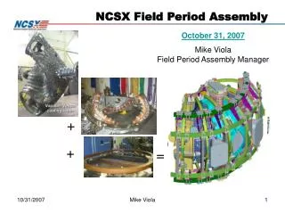
Field Period Assembly
Field Period Assembly. Slides for discussion Rev 3. (VV Prep). Stage 1. (Half Period Assembly). Lower segment, shim and fasten. Stage 2. (MC installation). Stage 3. (Final FP Assembly). Stage 4. VV Prep Stage. Earlier installation orientation. Lower segment, shim and fasten.


Field Period Assembly
E N D
Presentation Transcript
Field Period Assembly Slides for discussion Rev 3
(VV Prep) Stage 1 (Half Period Assembly) Lower segment, shim and fasten Stage 2 (MC installation) Stage 3 (Final FP Assembly) Stage 4
VV Prep Stage Earlier installation orientation
Lower segment, shim and fasten MC segment alignment system Half Field Period Assembly
Final Field Period Assembly Figure 7a Initial TF Placement Figure 7b) Initial TF Placement Figure 7 Final Full Period Assembly
34.8’ 21.25’
Stage 3 Stage 1 TF FP Stage 4 Stage 2
It is assumed that there is some form of pre-assembly of the TF coils
Se185-009.asm 23,000 lbs Se185-006.asm 3,203 lbs Se185-005-01.asm 6,000 lbs Se185-008.asm 4,012 lbs 18,700 Se185-007.asm 2,660 lbs Se185-004.asm 2,825 lbs Total 41,700 lbs
MCAF Component Details Module Coil Half Period (25000 lbs) MCHP / Turning Fixture interface Pivot and rotation component (3200 lbs) Cradle component (6000 lbs) Vertical guide component (4000 lbs) 18,700 lbs (2700 lbs) Linear turntable structure Linear motion structure (2800 lbs)
RY = 13° RX = 5° DZ = 16” RZ = 15° DX = 12” Z Y X DY = 140” Total Weight of Reference Turning Fixture is ~18,700 lbs (assumes steel construction) • Design uses: • structural steel components • worm gear screw assemblies • rollers
Vacuum Vessel Period Module Coil Half Period Module Coil Half Period
Sideways clearances between MC shell and secondary support structure shall be greater that 60”
Gantry Crane Module Coil Half Period Turning Fixture / MC Interface Components Module Coil Half Period Type “C” Turning Fixture Type “A” Base Guide Rail VV Support Type “B”
Gantry Crane Module Coil Half Period Module Coil Half Period Turning Fixture Base Guide Rail
Y Y X Z Rz X Rx X Ry . X Z
Length of screw shown is 172” If we allow a rotational extraction of the MCHP it looks like we can come under the 144” max length of the screw. A 144” screw would reduce the 63’ space savings by 28”, leaving 35” of space. 63” potential space savings.
Max stress = 11 ksi Max Disp = .09 in Load = 23,000 lbs Total Unit weight = 36,410 lbs
Starting Position - CG Locations (Base End and Front Views) 18,300 MCFP 38,000 MCAF
89.1” Starting Position - CG Locations (End and Top Views from Vertical Guide Structure) 18,300 MCHP 38,000 MCAF
Final Position - CG Locations (Front and Top Views from Base Structure) 18,300 MCHP 38,000 MCAF 100.0”
0.54” 74” 82” 1 1 3 2 2 3
Machine Coordinate System Y Z 60 Deg X Baseline MCAF Coordinate System 66.753”
C5 B5 A5 C4 A6 B4 B6 A4 C6 A3 C1 B3 B1 C3 A1 C2 B2 A2 Half Period Assembly Sequence – perform all alignment and hole placement at this stage.