Avalanche gain in HgCdTe
290 likes | 569 Views
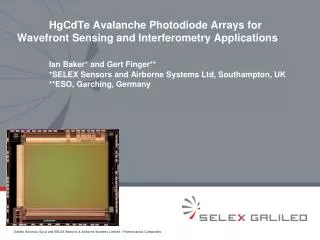
HgCdTe Avalanche Photodiode Arrays for Wavefront Sensing and Interferometry Applications Ian Baker* and Gert Finger** *SELEX Sensors and Airborne Systems Ltd, Southampton, UK **ESO, Garching, Germany. Avalanche gain in HgCdTe. HgCdTe – a unique material

Avalanche gain in HgCdTe
E N D
Presentation Transcript
HgCdTe Avalanche Photodiode Arrays for Wavefront Sensing and Interferometry ApplicationsIan Baker* and Gert Finger** *SELEX Sensors and Airborne Systems Ltd, Southampton, UK **ESO, Garching, Germany
Avalanche gain in HgCdTe • HgCdTe – a unique material • Electron/hole mass ratio very large – electron gets all the energy – single carrier cascade process gives low added noise • The conduction band of HgCdTe devoid of any low-lying secondary minima, which allows for large electron energy excursions deep into the band, and hence the high probability of impact ionization, with the generation of electron-hole pairs. • Avalanche photodiodes • Voltage controlled gain at the point of absorption • Almost no additional noise • Near-zero power consumption • Up to GHz bandwidth • Requires no silicon real estate Quite a useful component!
Avalanche gain v. bias volts and cutoff wavelength HgCdTe avalanche photodiodes at 77K Cut-off wavelength [μm]
Avalanche gain v. bias volts and cutoff wavelength HgCdTe avalanche photodiodes at 77K Cut-off wavelength [μm] Used for Burst Illumination LIDAR (BIL) imaging Potential for low background flux astronomy
HgCdTe technology options for APDs n p APD array using via-hole process LPE HgCdTe layer grown on CdZnTe substrate HgCdTe monolith bonded to ROIC LPE material + via-hole hybrid technology - Currently gives best breakdown voltages Bump bonded to ROIC Multi-level APD design MOVPE HgCdTe layer grown on 75mm GaAs substrate MOVPE material + mesa hybrid technology - Under development for APDs
Silicon multiplexer (ROIC) options ME770 – Dual Mode 256x320 on 24µm pitch Thermal imaging OR BIL imaging Thermal image BIL image ME780 - Swallow 3D 256x320 on 24µm pitch 3D intensity and range per pixel BIL intensity image BIL range image Both ROICs can be configured to run in non-destructive readout. Parasitic capacitance is higher than a custom ROIC but results can allow for this. Both used for ESO APD study
Pixel to pixel uniformity of avalanche gain No avalanche gain Gate - 3900ns Avalanche gain - 4.6 Gate - 800ns Avalanche gain - 13.8 Gate - 300ns Avalanche gain - 38 Gate - 100ns Short and long range uniformity of avalanche gain – no issue for data acquisition
Noise after avalanche gain Noise proportional to: Gain . sq rt (gate time . noise figure) Detailed measurements givenoise figure of1.3 up to x97 gain Extra noise due to avalanche process negligible
Array operability performance – BIL compared with SW Noise spatial distribution for typical BIL detector Temp - 100K Wavelength – 4.5 μm Gate time - 160ns Ava. gain - x25 Very few defects due to short gate time The low pixel defect count of BIL detectors is due to the short gate time. Wavefront sensors need 3e5x longer integration time so dark current critical
Avalanche gain for wavefront sensors How does avalanche gain benefit wavefront sensors? Typical requirement: Integration time – 1.0 to 5.0 ms Waveband – 1.0 to 2.5 µm Multiple non-destructive readouts Sensitivity in noise-equivalent-photons (NEPh) – 3 photons rms [Note NEPh a better Figure of Merit for APDs]
Noise-equivalent-photons (NEPh) - sensitivity figure of merit for APDs Allows for photon noise
SELEX APD Pre-development Programme for ESO ME770 – Dual Mode 2.50 μm 3 variable jn hybrids 5 full hybrids 2.54 μm 2 FPAs to ESO in flatpacks ME780 - Swallow 3D 2.64 μm 2 variable jn hybrids 4 full hybrids SW LPE HgCdTe layers 2 FPAs to ESO in flatpacks
Experimental hybrid with variable junction diameters Variable junction diameter
Result of variable junction diameter experiment Better signal with smaller junction No effect on avalanche gain Conclusion: use small junction diameters on further arrays
ESO measurements on variable jn diameter array Data: Integration time – 3ms Temperature – 60K Cut-off – 2.64 μm ESO measurements show strong S/N benefit from using small junctions
NEPh v. Bias Volts as function dark current - to set dark current specification Dark current (A/cm2) Data: Integration time – 5ms Temperature – 70K Wavelength – 2.5 μm Target dark current specification is <1e-11 A/cm2 (360 e/s)
Comparison of SELEX and ESO measurements of dark current v. temperature Target spec <1e-11 A/cm2 Array data: Cut-off wavelength – 2.64um Trap-assisted tunnelling behaviour ESO measurements Shows dark current specification is met for temperatures below 90K
Typical output from ESO Test Rig Signal Noise Shows that noise is limited by photon shot noise
ESO measurement of uniformity under moderate gain ROIC – ME784 Bias – 7.1V Temperature – 70K TBB - 100ºC-50ºC
ESO measurement of Avalanche Gain – comparison with model Measured data for 2.64 μm diode Fitted: APD Gain = 0.0782*2(Vbias/1.126)+0.905 Model for 2.64 μm diode (green) Model for 2.5 μm diode (red) ROIC – ME770 Temperature – 70K
ESO measurement of Quantum Efficiency – 70% ROIC – ME770 Bias – 8.63V Gain - 16x Temperature – 70K
ESO measurement of electrons per ADU to calibrate the detector test – 2.21 e/ADU ROIC – ME784 Gain of 6.4 Temperature – 80K Signal electrons – Q Noise electrons – Q0.5 Signal V = Q.e.T/C (Noise V)2 = Q.(e.T/C)2 Signal/(Noise)2 in ADUs = electrons/ADU T is pixel transfer function C is integration cap
ESO measurement of noise at gain of 6.4 ROIC – ME784 Temperature – 60K Aval. gain – 6.4 Integration time – 5ms
ESO measurement of noise at gain of 6.4 Theory for custom ROIC Theory for ME784 ROIC – ME784 Temperature – 60K Aval. gain – x6.4 Integration time – 5ms
Dark current defect map under extreme conditions – effect of temperature 45K 60K 70K 80K Reducing temperature reduces the number of high dark current pixels
Low photon flux imaging using avalanche gain Readout with avalanche gain of x1.5 Readout with avalanche gain of x7 FPA at 60K Average of 10 frames 6 electrons imaging
Modelled sensitivity based on measured data and with a custom ROIC Data: Integration time – 5ms Temperature – 77K Cut-off – 2.5um Avalanche gain offers an order improvement in NEPh
Conclusions on avalanche gain for wavefront sensing applications (A-O and interferometry) • Results so far • Avalanche gains up to x16 at 8.6V bias achieved in 2.64 μm material • 6 electrons rms achieved with existing non-optimised ROIC and electronics • Optimised technology could provide 2-3 photons rms • All the aspirations of wavefront and interferometric applications can be met by APD technology • Future work • Need to establish parameter space of APDs i.e. wavelength, temperature etc • Need to design custom ROIC