Sensor Configuration for Motion Testing
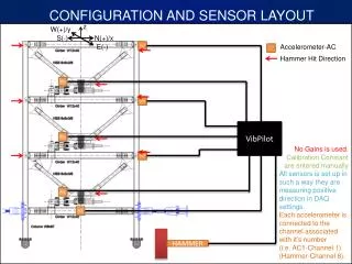
This configuration involves sensor layout and calibration for motion testing using accelerometers and a hammer. Sensors are set to measure positive direction in DAQ settings. Accelerometers are connected to their respective channels. Different sensor layouts are specified for in-plane and out-of-plane tests.

Sensor Configuration for Motion Testing
E N D
Presentation Transcript
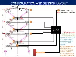
CONFIGURATION AND SENSOR LAYOUT z W(+)/y S(-) N(+)/x E(-) AC7 Hammer Hit Direction AC4 Accelerometer-AC AC6 VibPilot AC3 No Gains is used. Calibration Constant are entered manually All sensors is set up in such a way they are measuring positive direction in DAQ settings. Each accelerometer is connected to the channel associated with it’s number (i.e. AC1-Channel 1) (Hammer-Channel 8). AC5 AC2 AC1 HAMMER
DETAIL 1 DETAIL 3 DETAIL 1 DETAIL 3 DETAIL 1 DETAIL 3 DETAIL 2
SENSOR DETAILS FOR IN-PLANE TESTS*Refer to Detail 1a, 2 and 3 *These configuration is related to the tests where floor sensors are located outside of the flange aligned with web.
SENSOR DETAILS FOR IN-PLANE TESTS*Refer to Detail 1b, 2 and 3 *These configuration is related to the tests where floor sensors are located inside the flange.
D etail 1a In-Plane W10x30 W8x67 Di r e c tion of M easu r eme n t 5-1/4 ’ ’ Di r e c tion of M easu r eme n t In the trial descriptions, this case is referred as: “Aligned with Web”
D e t a i l 1b In-Plane W 1 0 x 3 0 W 8 x 6 7 D i r e c t i o n o f M e a s u r e m e n t 5 - 1 / 4 ’ ’ D i r e c t i o n o f M e a s u r e m e n t 2 - 3 / 8 ’ ’ In the trial descriptions, this case is referred as: “On the Flange”