Download
1 / 55
560 likes | 765 Views
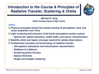
Introduction to the Course & Principles of Radiative Transfer, Scattering & Orbits. Michael D. King NASA Goddard Space Flight Center Outline Physical principles behind the remote sensing of atmosphere, land, and ocean properties from Terra

E N D
Introduction to the Course & Principles of Radiative Transfer, Scattering & Orbits Michael D. King NASA Goddard Space Flight Center Outline • Physical principles behind the remote sensing of atmosphere, land, and ocean properties from Terra • Light scattering and emission of the Earth-atmosphere-surface system • Spacecraft, spatial resolution, swath width, and sensor characteristics • Satellite orbits and repeat coverage required for global observations • Fundamental concepts and terminology of radiative transfer • Atmospheric absorption and transmission characteristics • Radiance & irradiance • Scattering phase function • Optical thickness • Single and multiple scattering
Remote Sensing Overview • What is “remote sensing”? • Using artificial devices, rather than our eyes, to observe or measure things from a distance without disturbing the intervening medium • It enables us to observe & measure things on spatial, spectral, & temporal scales that otherwise would not be possible • It allows us to observe our environment using a consistent set of measurements throughout the globe, without prejudice associated with national boundaries and accuracy of datasets or timeliness of reporting • How is remote sensing done? • Electromagnetic spectrum • Passive sensors from the ultraviolet to the microwave • Active sensors such as radars and lidars • Satellite, airborne, and surface sensors • Training and validation sites
Remote Sensing Applications to be Covered in this Course • History of remote sensing & global change • Remote sensing of land surface properties • Spectral and angular reflectance, land cover & land cover change • Fire monitoring and burn scars • Leaf area index & flux of photosynthetically active radiation • Temperature & emissivity separation of terrestrial surfaces • Remote sensing of atmospheric properties • Cloud cover, cloud optical properties, and cloud top properties • Aerosol properties • Water vapor • Atmospheric chemistry (carbon monoxide and methane) • Earth radiation budget and cloud radiative forcing • Remote sensing of the oceans from space • Chlorophyll concentration and biological productivity of the oceans • Sea surface temperature using thermal methods • Angular directional models of the Earth-atmosphere-ocean system
The Electromagnetic Spectrum • Remote sensing uses the radiant energy that is reflected and emitted from Earth at various “wavelengths” of the electromagnetic spectrum • Our eyes are only sensitive to the “visible light” portion of the EM spectrum • Why do we use nonvisible wavelengths?
Schematic Wave of Radiation Visible Spectrum 0.4 0.5 0.6 0.7 Wavelength (µm) From Parkinson, C. L., 1997: Earth from Above
Spectral Characteristics of Energy Sources and Sensing Systems
Basic Interactions between Electromagnetic Energy and the Earth’s Surface
Generalized Spectral Reflectance Envelopes for Deciduous and Coniferous Trees
Typical Spectral Reflectance Curves for Vegetation, Soil, and Water
Atmospheric Effects Influencing the Measurement of Reflected Solar Energy
Atmospheric Transmission Spectra UV VNIR SWIR MWIR LWIR 1.0 0.8 0.6 Transmission 0.4 0.2 0.0 0.2 1 10 25 Wavelength (µm)
Low Earth Orbit Concepts Descending node Ascending node Perigee Ground track Orbit Inclination angle Equator Orbit South Pole Apogee
Satellites in Geosynchronous Orbits are used as Relay Satellites for LEO Spacecraft Imaging System (e.g., Terra) LEO Communication relay system Ground station GEO Communication relay system (e.g., TDRSS)
Scattering of Sunlight by the Earth-Atmosphere-Surface System A = radiation transmitted through the atmosphere and reflected by the surface B = radiation scattered by the atmosphere and reflected by the surface C = radiation scattered by the atmosphere and into the ‘radiometer’ G = radiation transmitted through the atmosphere, reflected by background objects, and subsequently reflected by the surface towards the ‘radiometer’ I = ‘adjacency effect’ of reflectance from a surface outside the field of view of the sensor into its field of view
Thermal Emission from the Earth-Atmosphere-Surface System D = radiation emanating directly from the target E = radiation emanating from the atmosphere downward and subsequently reflected by the surface towards the ‘radiometer’ F = radiation self-emitted by the atmosphere H = radiation emitted by background objects and subsequently reflected by the target into the direction of the observer F H D E
dF dA Irradiance (Flux per unit Area) E = irradiance = flux per unit area [Wm-2] = q E0 Eq = E0 cosq E0
dA r2 Element of Solid Angle dW= [sr]
d2F dE dWcosq dAcosqdW Intensity (or Radiance) I = flux per unit area per unit solid angle normal to the direction of propagation [Wm-2sr-1] = = I q N
Projected Area Effects on Irradiance • Irradiance crossing area Aq at angle of incidence q is reduced from that on a normal surface due to the growth in cross sectional area P N E0 Au N Aq = Au/cosq q P E0 Au N q P E0 q Eq = E0cosq Au
Solid Angle Representation on Spherical Coordinates z dW= sinqdqdf rsinqdf rsinq rdq df q dW dq x f df y
Angular Scattering Coefficient • Angular scattering coefficient [b(Q)] • Fractional amount of energy scattered into the direction Q per unit solid angle per unit length of transit [m-1 sr-1] Q dW Unit length Propagating beam f Scattering center
Volume Scattering and Extinction Coefficient • Volume scattering coefficient [ssca] • Fractional amount of energy scattered in all directions per unit length of transit [m-1] ssca = = • Volume absorption coefficient [sabs] • Fractional amount of energy absorbed per unit length of transit [m-1] • Volume extinction coefficient [sext] • Fractional amount of energy attenuated per unit length of transit [m-1] sext= ssca + sabs • Single scattering albedo [0] • Fraction of energy scattered to that attenuated 0 = ssca/(ssca + sabs)
Optical Thickness • Optical depth [t] • Total attenuation along a path length, generally a function of wavelength [dimensionless] • Total optical thickness of the atmosphere [tt] • Total attenuation in a vertical path from the top of the atmosphere down to the surface • Transmission of the direct solar beam t =exp[-tt(l)/µ0] t =exp[-tt(l)] q0 µ0 = cosq0
Scattering Phase Function • Scattering phase function is defined as the ratio of the energy scattering per unit solid angle into a particular direction to the average energy scattered per unit solid angle into all directions with this definition, the phase function obeys the following normalization • Rayleigh (molecular) scattering phase function
Shapes of Scattering Phase Function Rayleigh (molecular) Composite 90° 135° 45° 180° 0° 225° 315° 270°
Shapes of Scattering Phase Function 90° Nonselective scattering 135° 45° Mie scattering 180° 0° 225° 315° 270°
Composition of Atmospheric Transmission Exoatmospheric solar irradiance 104 1.0 Exitance (300 K) 103 102 Irradiance (Wm-2µm-1) 101 0.5 Transmission 100 Atmospheric transmission 10-1 10-2 0.0 0.2 1 10 25 Wavelength (µm)
Absorption Properties of the Earth’s Atmosphere 0 0 50 50 H2O 100 100 0 0 50 50 O3 100 100 Absorption 0 0 50 50 CO 100 100 0 0 50 50 CO2 100 100 0 2 4 6 8 10 12 14 Wavelength (µm)
Absorption Properties of the Earth’s Atmosphere 0 0 50 50 CH4 100 100 0 0 50 50 N2O 100 100 Absorption 0 0 50 50 O2 100 100 0 0 50 50 Total 100 100 0 2 4 6 8 10 12 14 Wavelength (µm)
Scattering of Sunlight by the Earth-Atmosphere-Surface System 2000 Exoatmospheric solar irradiance F0(l) 1500 Solar irradiance reaching the surface F(l) Irradiance (W m-2 µm-1) 1000 500 0 0 1 2 3 Wavelength (µm)
Definition of Solar Zenith, View Zenith, and Relative Azimuth Angle q0 q N f0 W f Df E S
Definition of Reflection Function The reflection function is defined by R(tt, w0; µ, µ0, f) = where tt = total optical thickness w0 = the single scattering albedo (ratio of scattering to total extinction) µ = absolute value of the cosine of the zenith angle |cosq| µ0 = cosine of the solar zenith angle cosq0 f = relative azimuth angle between the direction of propagation of the emerging radiation and the incident solar direction I = reflected intensity (radiance) in the outward (–µ) direction F0 = incident solar flux (irradiance) in W m-2 µm-1 Note: R, tt, w0, F0 and I are all functions of wavelength l pI(0, –µ, f) µ0F0
Flux (Irradiance) on a Horizontal Surface at the Surface of the Earth The transmitted flux (irradiance) at the Earth’s surface can be calculated as: where the transmission function is defined in an analogous manner to reflection function
Reflectance Properties of Idealized Surfaces ‘Lambertian’ Specular reflector Diffuse Less idealized surface Nearly diffuse Nearly specular
Bidirectional Reflectance Concept q0 q f0 f
University of Washington CV-580 Ames Airborne Tracking Sunphotometer (AATS) Solar Spectral Flux Radiometer (SSFR) Cloud Absorption Radiometer (CAR)
Goddard Space Flight Center developed in 1982-1983 University of Washington integrated & flown in 1984 (B-23) principal data from 1987-97 (C-131A) flights after 1998 (CV-580) Sensor Characteristics 14 spectral bands ranging from 0.34 to 2.29 µm scan ±95° from horizon on right-hand side of aircraft field of view 17.5 mrad (1°) scan rate 1.67 Hz (100 rpm) data system 9 channels @ 16 bit 395 pixels in scan line 4% reflectance calibration accuracy Cloud Absorption Radiometer
Bidirectional Reflectance Measurements • Roll: ~20° • Time: ~2 min • Speed: ~80 m s-1 • Height: ~600 m • Diameter: ~3 km • Resolution • 10 m (nadir) • 270 m ( = 80°) • Channels • 8 continuously sampled (0.34-1.25 µm) • 2 filter wheel channels used for BRDF measurements (1.64 & 2.20 µm)
Bidirectional Reflectance - TundraMelt Season (q0 = 81°) l = 1.64 µm l = 0.67 µm 0.0 0.2 0.4 0.6 0.8 1.0
Bidirectional Reflectance - TundraMelt Season (q0 = 81°) Snow Free Tundra
Bidirectional Reflectance - Atlantic Ocean Sunglint (q0 = 19°) l = 1.64 µm l = 0.67 µm 0.0 0.2 0.4 0.6 0.8 1.0
Bidirectional Reflectance - Atlantic OceanSunglint (q0 = 19°) Atlantic Ocean (sun glint)
NASA Earth Science Spacecraft in Orbit TRMM 11/27/97 Landsat 7 4/15/99 QuikScat 6/19/99 Terra 12/18/99
NASA Earth Science Spacecraft in Orbit EO-1 11/21/00 Jason-1 12/7/01 SAGE III 12/10/01 Aqua 5/4/02
EOS Spacecraft Under Development SORCE 12/02 ICESat 12/02 Aura 1/04