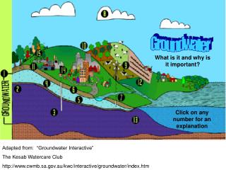
Groundwater
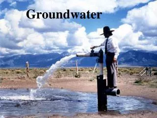
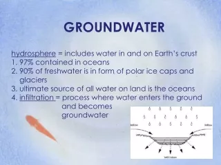
Groundwater. Of the roughly 350 billion gallons of fresh water withdrawn per day in US, 24% from groundwater 16 million pumping water wells in US for public and private supply, irrigation, livestock, manufacturing, mining, thermoelectric power, and other purposes 15.4 million private wells

Groundwater
E N D
Presentation Transcript
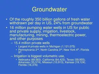
Groundwater • Of the roughly 350 billion gallons of fresh water withdrawn per day in US, 24% from groundwater • 16 million pumping water wells in US for public and private supply, irrigation, livestock, manufacturing, mining, thermoelectric power, and other purposes • 15.4 million private wells • Largest # private wells in Michigan (1,121,075) • Pennsylvania 2nd, North Carolina 3rd, New York 4th, Florida 5th. • Irrigation is biggest volumetric use, • Nebraska (69,583), California (64,423), Texas (59,955), Arkansas (35,574), Missouri (10,913), Kansas (19,124), Florida (16,376)
America’s Largest Well • Kansas City Kansas • Horizontal collector well 135 feet below the surface • 40 MGD • 90% induced surface water recharge • 10% groundwater from aquifer
Washington Wells • Installation regulation by Dept. of Ecology • 72 hour notification • No water right needed, if <5000 GPD for domestic or industrial supplies and will irrigate less than ½ acre of lawn or non-commercial garden • Setbacks of 100 feet from contamination source (Septic tanks, privies, stockyards, etc.); 1000 feet for landfill • Must be installed by licensed installer; general contractors’s registration and insurance bond with DLI also necessary • Maybe additional local ordinances
Washington Well Laws and Regulations • Chapter 18.104 RCW WATER WELL CONSTRUCTION • Chapter 90.36 RCW ARTESIAN WELLS • Chapter 90.44 RCW REGULATION OF PUBLIC GROUND WATERS • Chapter 173-160 WAC, Minimum Standards For Construction And Maintenance Of Wells • Chapter 173-162 WAC, Regulation And Licensing Of Well - Contractors And Operators
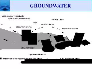
Aquifer Perched Confined Unconfined Regolith Unsaturated Zone (Vadose) Soil Saturated Zone (Phreatic) Water Table Capillary Fringe Infiltration Recharge Evapotranspiration Aquitard Aquiclude Clay lense Subsurface Terminology:
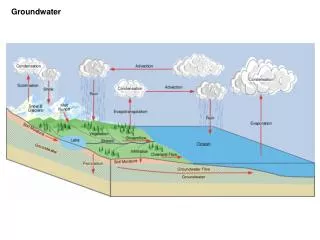
Every aquifer has a different make-up but the general components are the same. Components of an aquifer may include the unsaturated zone, capillary fringe/zone, groundwater table, saturated zone, and semi-confining or confining layers. Unsaturated zone (vadose zone or zone of aeration) The zone between the land surface and the water table. It includes the root zone, intermediate zone, and capillary fringe.The pore spaces contain water at less than atmospheric pressure, as well as air and other gases. Saturated bodies, such as perched groundwater, may exist in the unsaturated zone (Fetter 1988). Capillary fringe The zone immediately above the water table, where water is drawn upward by capillary attraction. The capillary fringe can be considered the "line" between the unsaturated and saturated portions of the aquifer. The thickness of this area varies as the water table moves up or down. However, the portion of the capillary fringe located close to where the 100% water saturation is reach is called the capillary zone.
Water Table (Phreatic Surface) • The water table, or phreatic surface, is an imaginary surface that bounds the saturated zone from above. It is defined as the surface at every point of which the water pressure is atmospheric. • The level of the groundwater table is typically the level to which water will rise in a well. • Rigorously, the well should be screened, i.e., hydraulically connected to the saturated zone at the phreatic surface.
Saturated zone (Phreatic Zone) • The saturated portion of the ground that lies in the water table. The zone in which the voids in the rock or soil are filled with water at a pressure greater than atmospheric. The water table is the top of the saturated zone in an unconfined aquifer.
Confined aquifer • Groundwater that becomes trapped under impermeable soil or rock may be under pressure. This is called a confined or artesian aquifer. • A well that pierces a confined aquifer is known as an artesian well . Water pressure in the confined aquifer will cause water in the well to rise above the aquifer level. • The maximum level that the water in the well will rise to is known as the potentiometric surface (Piezometric), or potential water level. If this is higher than the top of the well, the well will overflow.
Hydraulic Head (h): • h = z + p/ρg + v2/2g • z is the elevation head, height above a reference elevation • p is the gauge pore water pressure • g is acceleration due to gravity • v is velocity of water
Hydraulic Head z = elevation at point of measurement (relative to arbitrary datum z0) = elevation head = p/g = pressure head
Hydraulic head example Ground surface p h Point of measurement z Datum (usually at z=0)
Aquifer/ geological characteristics Observed • Aquifer type (consolidated/unconsolidated) • texture • homogeneity / sorting Measured/Calculated • porosity • anisotropy • conductivity • storativity
Porosity () • Determines the amount of water that can be stored in a saturated aquifer.
Anisotropy and isotropy Anisotropy: non-uniform flow resistance Heterogeneity: changes in geological structures over small distances
Determining Hydraulic Conductivity: • Solve Darcy’s equation for K • K = -q/(dh/dl) • Determine in lab using permeameter • Determine in field with pumping tests or slug tests
Specific Yield and Retention • Specific Yield (Sy)is the water that can be pumped from a well (or would drain under gravity) (Effective Porosity) • Specific Retention (Sr) is the portion of water which cannot be pumped out of well and is left as film on rock surfaces
Storativity and Specific Yield • Unconfined aquifer • Depth of water stored/unit decline in hydraulic head = Specific yield, Sy ~ porosity, n • Confined aquifer • Storativity, S, corresponds to Specific yield • Function of compressibility and proportional to aquifer thickness • Specific storage, Ss , = S/b • b= aquifer thickness
Types of Pumping Wells • Dug (wide, typically only 10-30 feet deep) • Driven (1.25 to 12 inches diameter, 30-50 feet deep) • Typically in areas with thick sand or gravel deposits and water table within 15 feet of surface) • Drilled (most 100-400 feet deep) • Cable tool • Percussion (5-10 feet section progresses) • (4-18 inches diameter up to 1000 feet deep; upper section +4” for grouting; depthe depends on geologic formation) • Rotary • (3-24 inches diameter, up to 1000 feet deep; upper section at least 2” wider) • Jetted (2-12” diameter, up to 50 feet deep) • (Casing for at least 25 feet and grouted to 10 feet) • Bored (2-30” diameter, up to 125 ft deep)
Well Cap Well Casing Well Sea Well Slab Pitless Adaptor Water Service Pressure Tank Drop Pipe Well Screen Gravel Pack Pump Well Components
Well Construction • Drilling Operation • Installing the Casing and Screen • Installing the Artificial Filter Pack • Grouting/Sealing the Well • Developing the Well • Installing Permanent Pump
Types of Wells • Drilled Wells • Deep (at least 100 feet, up to 1000 feet) • Most expensive to install • Installed with Rotary or Percussion drilling rigs • Bored or Dug Wells • <50 feet deep (bored wells may exceed 100ft) • Only a few feet into water table (up to 10 ft for bored) • Wider diameter (dug 2-30 feet; bored 2-30 inches) • Jetted Wells • Up to 100 feet • 2-12 inch diameter
Vented At least 6-8 inches above ground (generally 12” or more) Snug Fit Aluminum or Thermoplastic Well Caps Unacceptable Proper
Well Casing • Carbon Steel, PVC, or Stainless Steel • Determined by water chemistry and geology • Diameter affects well cost and efficiency • Deep wells and wells >4 inches casing chosen on basis of pump accommodation (nominally 2 sizes larger than pump; can be smaller below pump if screened much lower); for wells 4” or less 1 size larger than pump is adequate • Purpose to keep well from filling in • Three forces: • Tensile forces • Column loading forces • Collapse pressure
Drop Pipe • PE Pipe (generally single piece) • Not rated for hot water • Must no be kinked • Actual conveyance of water
Well Screen • Slotted openings; preferably continuous and uninterrupted around circumference • V-shaped widening inward • Single metal construction or plastic to avoid galvanic corrosion • Maximum open construction consistent with strength requirements
Pressure Tanks • Help preserve pump life • Help maintain adequate pressure at tap • Tanks typically constructed of lined metal • Older unlined tanks more susceptible to corrosion • Newer tanks have diaphragm to minimize water logging • Old tanks would become water logged and had to be drained and pumped with air
How pumps work • Suction pumps • Think of a drinking straw • Limited by physics; at sea level atmospheric pressure only 14.7 PSI or 34 feet of water • Practical lift 22-25 feet at sea level; decrease by 1 foot for every 1000 feet elevation • Jet Pumps (~32% U.S. homes, 8% double jet) • Shoot stream of water through small nozzle into venturi tube creates partial vacuum • Submersible Pumps (~60% U.S. homes) • Push water using series of impellers or turbines, rather than pull • Air-lift pumps (uncommon) • Uses bubbling of air to cause water to rise
Pumps • Shallow Well Pumps (typically <30 feet) • Piston Pump • Rotary Pump • Centrifugal Pump • Self-priming Pump • Single Jet pump • Deep Well Pumps • Double Jet Pump (production from up to 75-85 feet) • Submersible Pumps (up to 1000 feet) • Turbine, Rotary, Jet Pump • Deep Piston (up to 600 feet)
Pump Placement • Never directly at bottom of well • Typically 10-20 feet up from bottom of well • Placing inside recharge zone may create cascading water situation leading to sediment buildup in the well