Download

1 / 22
220 likes | 379 Views
Mapping for Silicon Run IIb. L. Bagby, A. Nomerotski, E. von Toerne December 2002 http://d0server1.fnal.gov/projects/run2b/Silicon/www/smt2b/readout/mapping.htm. Mapping/Cabling Requirements. Do not move the 80 conductor cables Do not move the 50 conductor cables Avoid cable knots

E N D
Mapping for Silicon Run IIb L. Bagby, A. Nomerotski, E. von Toerne December 2002 http://d0server1.fnal.gov/projects/run2b/Silicon/www/smt2b/readout/mapping.htm
Mapping/Cabling Requirements • Do not move the 80 conductor cables • Do not move the 50 conductor cables • Avoid cable knots • Each HV channel has channel from only one VRB • Each stave goes into one VRB (soft constr.) 80-cond. cable requirements (from STT / see B.Reay’s note) • Do not combine different stave types I,II,III,IV • Do not combine hybrids from different 30deg. sectors • Do not combine L0 with other layers • Do not combine L4 with other layers • Do not combine a layer with any other layer (soft constr.)
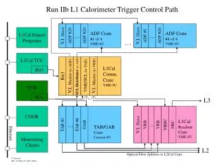
PwrPC PwrPC PwrPC 1 5 5 3 HV mod HV LV Bulk LV Power Supplies Fuse Panel I B Interface Board Crates (8x18) Cathedral Around Iteraction Region CLKs ~19’-30’ High Mass Cable (3M/80 conductor) 3/6/8/9 Chip HDI Adaptor card 8’ Low Mass Cables 3/6/8/9 Chip HDI CLKs CLKs 25’ High Mass Cable (3M/50 conductor) Cathedral Horse Shoe Sensor I,V,T Monitoring 17 twisted pair cables Optical Link 1Gb/s SEQ Sensor SEQ Controller Sequencer Crates (6x20) HV breakout box Serial Command Link VTM VRBC VRB S B C Platform 25 twisted pair cables VRB Crates (12x10) HV fanout 1=>4 VME Crates (4x3) HV Crates (8x6+2x4) MCH2 Monitoring SDAQ PDAQ (L3) MCH3 MCH2 PowerPCs and Single Board Computers are accessed thru Ethernet
Readout Electronics • SEQuencers • 6 crates (120 boards) located on the detector platform • Use SVX control lines to actuate acquisition, digitization and readout • Convert SVX data to optical signals • VRBs (Readout Buffers) • 12 crates (120 boards) located in counting house • Data buffer pending L2 trigger decision • Input @ 5-10 kHz L1 accept rate ~ 50 Mb/s/channel • Output @ 1 kHz L2 accept rate ~ 50 Mb/s • Interface Boards • 8 crates (144 boards) located inside the detector volume • Regenerates signals • SVX monitoring and power management • Bias voltage distribution
Installation Interface Boards
HV distribution HV Modules (MCH2) Fanout Boxes (MCH2) Breakout Boxes (Platform)
Naming of Installed Parts A few technical terms Module: A sensor/hybrid combo in Layers L2-5 Types: 10/10A 20/20A 10/10S 20/20S Stave: 10/10A+20/20A+10/10S+20/20S+support Ladder: Sensors ganged together in readout (1 Module = 2 Ladders)
General Remarks • Labeling of production parts and installed parts differs • Worst case naming scenario:Each subgroup uses different names for the same installed object:HV naming different from DAQ naming different from reconstruction different from MC simulation ... • It might be convenient to have a scheme similar to RunIIa • Because it is convenient not to have to learn new names • It might be better NOT to have a scheme similar to RunIIa • Because the detector geometry is very different and the naming should reflect the geometry. • The proposed scheme is a good compromise of these two principles
Module Position on Stave 20/20 South End North End 10/10 Naming of ladders: Lisa will use “barrel” label
Stave Location in R-phi Uli Heintz’s STT labeling (from Bill Reay’s mapping note) No inner/outer radius stave structure
Stave Location in R-phi End-on view • Compromise between STT note and reconstruction needs • Label with 3 digits • highest significant digit indicates layer • Start at x-axis, similar to U.Heinz’s STT note) • Go counterclockwise • Odd numbers have always smaller radius than even numbers in the same layer, consis-tent with Table 9, TDR 508 510 506 509 507 408 511 505 410 409 407 406 512 504 306 411 305 405 308 307 304 513 503 204 412 404 514 205 203 502 309 303 413 206 202 403 310 302 515 L5-01 414 207 L2-01 402 311 L3-01 516 530 415 208 212 L4-01 517 209 211 529 312 318 416 313 317 424 210 518 417 423 528 315 316 314 527 519 418 419 421 422 526 • North/South,Axial/Stereo labels: AN, AS, SS, SN 520 521 420 525 Seen from South(?) 523 522 524
Naming of Layer 0 and 1 4 End-on view 5 3 6 2 7 1 12 8 11 9 10
Naming of Layer 0 and 1 Sensors North End South End 6 5 4 3 2 1 1 2 3 4 5 6
Naming of Module/Staves – Part2 • How to address a sensor located inside the run IIb detector? • Usestave number and local sensor number • It is in layer 3, North side, Axial alignment • in an outer radius stave (because of even stave number) • the 6th sensor from the middle of the detector => outermost sensor on the north side • Advantage: Everybody is able to find it using the map • Hybrid locations are labeled by module L3-08NA-6
Naming of Production Parts, Hybrids • Name of Production parts conveys part properties. • Hybrid properties to appear in naming: • Layer 0 / L1 / L2-5 Axial / L2-5 Stereo • I suggest to label production hybrids with a 4-digit number, following a suggestion by Jim Fast • Highest significant number could indicate the hybrid type Example: Hybrid-0001 Layer0 Hybrid-1001 Layer1 Hybrid-2001A Layer2-5 Axial Hybrid-3001S Layer2-5 Stereo How does the database handle preceding 0’s ? Does the database accept hyphens? How do we handle pre-production parts? Highest Significant Digit
Naming of Production Parts, Sensors • Layer 0 / L1 / L2-5 • production sensors with a 4-digit number • The highest significant number indicates the sensor type Highest Significant Digit
Naming of Production Parts, Modules • L2-5 Modules named after hybrid they contain • + appendix to indicate 10/10 and 20/20 Modules • Hyb-2001A (L2-5, axial hybrid) becomes either • M-2001-10/10A or • M-2001-20/20A Naming of junction cards/adapter cards • No differentiation by layer • Assign consecutive production numbers
Naming of L0 flex cables • Assign production numbers based on layer and length -> will talk to Noel Naming of jumper cables • Differentiation by length Naming of twisted pair cables • Consecutive production numbers
Naming of Production Parts, Staves • Are all staves alike? Yes! • We can label staves with consecutive production numbers: Stave-1, Stave-2, Stave-3, … Stave-199 … • Once the staves are installed, they receive numbers that indicate their location. Location numbers and production numbers will be different and can be mapped onto each other using the database. • The map can be put into excel and posted on the web. • That way everybody will know where his/her favorite stave/hybrid/sensor ended up. This knowledge is important for the operation of the detector.