Download
1 / 26
260 likes | 374 Views
New particle ID detector for Crystal Ball at MAMI-C. Daniel Watts, University of Edinburgh John Annand 1 , B. Briscoe 3, A. Clarkson 2 , Evie Downie 1 , D. Glazier 2 , S. Lumsden 2 , Daria Sokhan 2 , C McGeorge 1 ,Claire Tarbert 2 1- University of Glasgow 2- University of Edinburgh

E N D
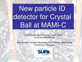
New particle ID detector for Crystal Ball at MAMI-C Daniel Watts, University of Edinburgh John Annand1, B. Briscoe3, A. Clarkson2, Evie Downie1, D. Glazier2, S. Lumsden2, Daria Sokhan2, C McGeorge1,Claire Tarbert2 1- University of Glasgow 2- University of Edinburgh 3- George Washington university
PID-I • Constraints of MWPC-I • and targets → siting of PMTs • at downstream end • Design specifications • Good separation of • p, p with little overhead • in material before MWPC • and CB detectors
MWPC-II & PID-II • MWPC-II redesigned for MAMI-C experiments • PID-II outside MWPC inbetween the MWPC chambers → Opted for setup similar to PID-I • ButPMTs at upstream end - TAPS
PID-II schematic PID-II schematic • PID-II – removable! • (redesigned MWPC connectors) • rPID-II >rPID-I • Keep same segmentation (24) • tscint = 4mm (PID-I: 2mm) FPID(INNER) = 108.4mm FMWPC = 133mm PMTs 500mm g beam PMT support ring MWPC Chambers MWPC supports CB Tunnel PID-II scintillators Hamamatsu H3164 - 10
PID-II – schedule and status months Delivery of scint. Total construction time ~ 5.2 months Cutting & prep of scint. 7 Lightguide manufacture Element assembly & tests Delivery of PMTs Detector assembly & tests Implementation into MWPC & CB ~1.5 month delay - Replacement of scintillator strips. New batch of manufactured by ELJEN
Al support ring Scintillator 3He target nose PMTs HV input and signal readout
PID-II GEANT Simulation Pions K+ Energy deposited in PID-II (GeV) Protons Energy deposited in CB (GeV) • Use PID-I simulation parameters – light output, light collection efficiency, QE … • → Reasonable agreement with experimental data • Include increase in PID-II scintillator thickness Flat KE distribution up to 0.7 GeV Isotropic angular distribution No shower shape restrictions
3 day old bananas - all PID2 elements 4 Proton punch through 1 PID2 Ebergy (a.u) 5 6 3 2 CB Energy (MeV) 8 9 7 10 11 12 16 15 17 14 18 13 20 22 21 19 24 23 Data from 3He target - NOq restriction or correction for path length in the scintillator
Summary • Detector ready for use
Data from first test PID2 Protons • PID Trigger – CH2 target • All 24 elements give good • signals Pions PID1
Radius mwpc = 66.5cm Liquid hydrogen target
PID-II test module – light attenuation • 90Sr beta source • Observe position of landau as source moved along scintillator • → light attenuation Active detector region Enhancement near PMT PID-II Test module PID-I Test module Position of landau peak (arb units) Distance from PMT (mm)
Schematic of PID-II for use with the Crystal Ball@MAMI-C D. Watts 20/04/06 Chamber length (between the supports) = 570 mm FMWPC = 133mm (outer diameter of PID support ring) FPID(INNER) = 108.4mm (inner diameter of PID ring) PMTs 500mm scintillator length g beam BEAM PMT support ring Plastic downstream scintillator support finner = 113.25mm (For detail see additional figure) MWPC Chambers MWPC supports CB Tunnel PID-II Scintillators finner = 116.4mm Hamamatsu H3164 - 10
PID-II • PID-I support ring router-rinner = 14mm • 4 mm clearance each side to the polarised target. Hydrogen target will have problem – clearance = 0mm! 51,5 65.5
PID-II PMTs • Same tubes and bases as for PID-I • BUT use new packaged tube + base assemblies -include magnetic shield • Hamamatsu H3164 - 10
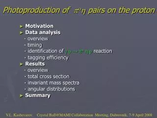
Preliminary decay gammas from nucleon knockout 12C(g,ppp)9Li Eg=400-500 MeV 2.69 MeV Low energy clusters from shaded region Q value Missing Energy (MeV) = Eg –STpi –Trec Energy of cluster (MeV) 3 i=1 • Also look at pp, 4p, 5p … knockout
Simulatedp+ signals in Crystal Ball ≤ 2 crystals in p+ shower No restriction on shower size m+ decay Highest cluster energy (GeV) Nuclear interaction Incident p+ energy (GeV)
Very preliminary decay gammas from nucleon knockout 12C(g,ppp) 2.69 MeV Low energy clusters from shaded region Q value
PID-II – schedule and status • rPID-II >rPID-I • Same segmentation (24) • Lscint chosen to give PID Info for all proposed targets • Lscint =50 cm (PID-I 32cm) PID-II Test module PID-I Test module