
r 1
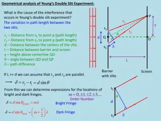
P. r 1. y. s 1. r 2. q. Q. d. O. d. s 2. L. Barrier with slits. Screen. s 1. q. d. d. s 2. Geometrical analysis of Young’s Double Slit Experiment:. What is the cause of the interference that occurs in Young’s double slit experiment?.

r 1
E N D
Presentation Transcript
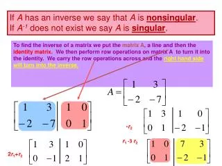
P r1 y s1 r2 q Q d O d s2 L Barrier with slits Screen s1 q d d s2 Geometrical analysis of Young’s Double Slit Experiment: What is the cause of the interference that occurs in Young’s double slit experiment? The variation in path length between the two slits. r1 – Distance from s1 to point p (path length) r2 – Distance from s2 to point p (path length) d – Distance between the centers of the slits L – Distance between barrier and screen y – height above centerline QO q – angle between QO and QP d – path difference If L >> d we can assume that r1 and r2 are parallel. From this we can determine expressions for the locations of bright and dark fringes. Order Number Bright Fringe Dark Fringe
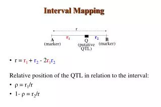
y q d L 1st 1st 0th The fringe pattern from a Young’s Double Slit experiment is shown above. Notice that there is a regular geometric pattern. The brightest fringe is located in the center of the pattern and is called the zeroth order maximum (m = 0). The first order maximums are the bright fringes, located a set distance from the 0th order fringe. One is located in the positive horizontal direction ( m = 1) and one in the negative horizontal direction (m = -1). You can also determine second order, third order etc. The dark fringes occur at half-orders (1/2, 3/2, 5/2, etc.) The location of the light and dark fringes can be determined from geometry. We will assume that L >> d and that d >> l, therefore we can use the small angle approximation. You should be able to see that this is a valid assumption. These expressions are often used to find l.
The intensity of the bright fringes is actually a gradual change between the center of the bright fringe and the center of the adjacent dark fringe. There is also an overall intensity change for the pattern as you move away from the zeroth maximum. The intensity change is due to varying degrees of constructive and destructive interference. The intensity is directly related to the electric field of the light wave. The two identical waves (one from each slit) will be slightly different. The different path lengths will introduce a phase shift between the waves. The phase shift can be determined from the difference in path length. When d = l/2, f = p d = l, f = 2p d is some fraction of l. f is the same fraction of 2p.
The intensity of the light at any point is defined by the combination of the two light waves at that point. We need to use the principle of superposition to determine the resultant wave from the two incident waves. Use the trig identity: When f is an even multiple of p you get constructive interference, and when it is an odd multiple of p you have destructive interference. Amplitude The intensity is proportional to the square of the electric field. We will look at the average intensity over time, since we are not interested in the fluctuations in the intensity in time. Time average of this function = 1/2 For a vacuum. Max intensity For small q. Intensity changes with vertical position!
A planar wave is incident on a pair of slits whose whose width and separation are comparable to the wavelength of the incident wave. Seen on a screen behind the slits is/are 1. two spots, one behind each slit. 2. only one spot, behind the center of the pair of slits. 3. many spots distributed randomly. 4. many spots distributed evenly.
The pattern on the screen is due to a narrow slit that is 1. horizontal. 2. vertical.
An interference pattern is formed on a screen by shining a planar wave on a double-slit arrangement (left). If we cover one slit with a glass plate (right), the phases of the two emerging waves will be different because the wavelength is shorter in glass than in air. If the phase difference is 180°, how is the interference pattern, shown left, altered? 1. The pattern vanishes. 2. The bright spots lie closer together. 3. The bright spots are farther apart. 4. There are no changes. 5. Bright and dark spots are interchanged.
Laser light passes through two small slits and strikes a screen, as seen in the photograph of the apparatus at the left below. A double slit interference pattern, like that shown at the right below, is produced. Which of the selections is the correct pattern after one of the slits is blocked off? Now the LEFT slit (as you look along the optic axis in the direction the beam is moving) is closed by sliding a small piece of metal in front of it. What will the pattern look like after the left slit is blocked off? (1) (2) It looks like the first choice is the same as the original pattern (the pattern does not change); the second looks the same except that its intensity is less (only one slit is open); the third looks similar, but without all of the little ridges; the fourth and the fifth appear to be images of only one of the slits, where one is inverted and the other is not. (3) (4) (5)


![I µ 1/[ R ln( R / r 0 )]](https://cdn1.slideserve.com/3032084/slide1-dt.jpg)


![I µ 1/[ R ln( R / r 0 )]](https://cdn4.slideserve.com/9143649/slide1-dt.jpg)