Download
1 / 32
330 likes | 435 Views
Enhance your B737-800 flight simulator with real-world surface roughness models, improving cockpit response to pavement conditions. Develop runway and taxiway rating scales based on pilot feedback. Get detailed insights and challenges resolved.

E N D
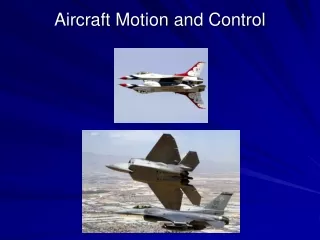
Full-Motion Aircraft Simulator Enhancements to Improve Cockpit Response to Pavement Roughness Skip Hudspeth and Gordon Hayhoe
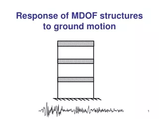
Pavement Roughness Subjective Pilot Rating Study • Phase I - Develop a surface roughness model on the B737-800 flight simulator for input of real world airport surface elevation profiles. • Phase II - Develop runway and taxiway pavement roughness rating scales for determining pavement condition for maintenance. The rating scales will be based on pilot's subjective ratings in response to simulator cockpit motions.
Acknowledgements FederalAviation Administration
B737-800 Simulator Overview • Surface Roughness Model Enhancements • Challenges and Resolutions • Roughness Model Testing • Future Work
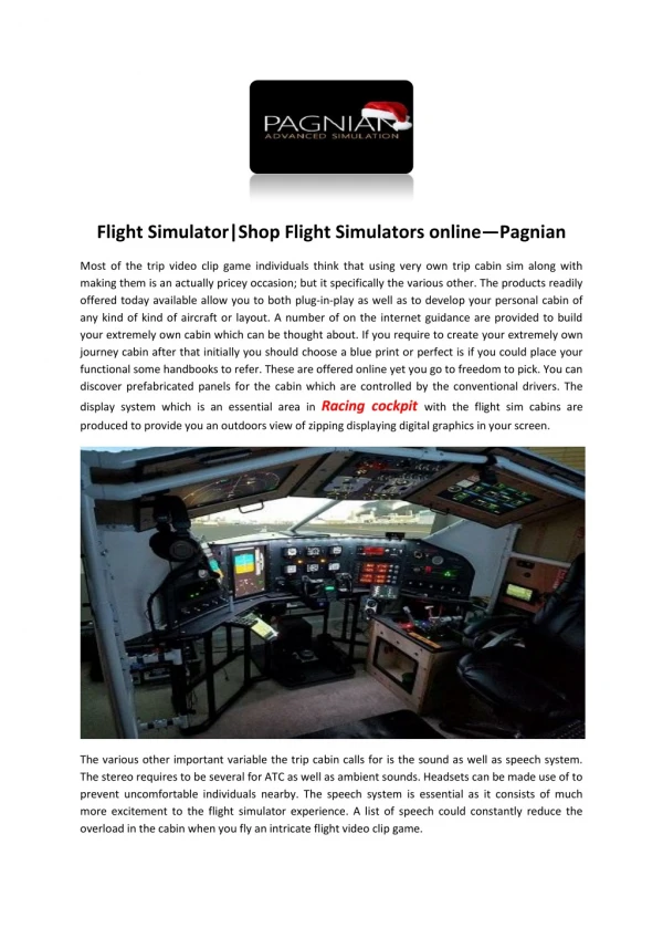
FAA B737-800 Flight Simulator Located at the FAA’s Mike Monroney Aeronautical Center in Oklahoma City. Level D Full Flight Simulator Six-degree-of-freedom motion system. High resolution visual display and sound system. Does not provide real world surface roughness models
Flight Simulator Overview Visual Image Generator Visual Display Flight Compartment Host Computer Interface Motion Control Cabinet Motion Platform
Flight Simulator Overview Visual Image Generator Visual Display Flight Compartment Host Computer Interface Motion Control Cabinet Motion Platform
Flight Simulator Overview Visual Image Generator Visual Display Flight Compartment Host Computer Interface Motion Control Cabinet Motion Platform
Flight Simulator Overview Visual Image Generator Visual Display Flight Compartment Host Computer Interface Motion Control Cabinet Motion Platform
Simulator Motion System • Due to limited travel, sustained accelerations are not possible. • Motion system designed to provides acceleration onset cueing. • Flight model accelerations are filtered to optimize the available motion response for training maneuvers. • An accelerometer mounted below the pilot seats provides measurement of cockpit vertical accelerations.
Motion System Inputs from the Flight Model • Receives rigid body accelerations from flight model • Other motion effects are simulated through the use of buffet and special effects generators within the motion system. • These include stall and flap buffets, touchdown bumps, etc.
Flight Simulator Overview Visual Image Generator Visual Display Flight Compartment Host Computer Interface Motion Control Cabinet Motion Platform
Flight Model Overview Simulator Flight Model Thrust Weight Atmosphere Ground Aerodynamics Equations of Motion Simulator Motion System Simulator Visual System
Existing B737-800 Simulator Surface Roughness Model • The simulator provides a generic roughness model using randomly generated vertical surface deviations. • The generic roughness amplitude is selectable with range from 0 to 5.
Random vs Actual Surface Roughness Generic (random) surface roughness Regional heavy runway surface roughness
New Surface Roughness Model • Replaces the random roughness generation with profiles measured on airport pavements. • Allows selection of surface profiles from simulator instructor station. • Integrates with existing simulator models. • Aligns airport surface profiles with visual scenes. • Provides realistic simulator cockpit motion.
Surface Profiles Formatted for use on the Simulator • Surface elevation is uniform across width of the profile. • Elevation units changed from inches to feet. • Surface profile sample spacing of four feet. • Profiles were filtered to remove very low frequency variations in elevation.
Profile Filtering Example Runway elevation profile before high-pass filtering Runway elevation profile after high-pass filtering
Integration of Surface Roughness Profiles into the Simulator Flight Model Gear Forces Surface Profile Strut Model
Flight Model Generates CG Accelerations Linear /rotational accelerations at CG Surface Profile Strut Model Flight Model
Motion System Transforms CG into Cockpit Accelerations Surface Profile Strut Model Flight Model Motion System
Aircraft Flexible Modes • The simulator flight model assumes a rigid aircraft body. • However, aircraft body flexing provides a large component of the cockpit acceleration response to surface roughness.
Cockpit vertical accelerations with rigid body modes Cockpit vertical accelerations with rigid body and four flexible body modes
Flexible Mode Simulation • Assumes lightly damped linearly flexible continuous body. • Four flexible modes were modeled. • Implemented on the host computer. • Strut force used to excite the flexible modes. • Outputs vertical accelerations at the cockpit position. • Cockpit vertical accelerations were transformed into CG pitch accelerations for transfer to the motion system.
Surface Roughness Model Evaluation • Tests were developed to evaluate the roughness model performance through the collection of time histories of aircraft and surface profile parameters such as: • Landing gear position along profile • Surface height at each gear position • Ground speed • Landing gear vertical force • C0mputed cockpit vertical acceleration • Actual cockpit vertical acceleration
Effect of ground speed on cockpit accelerations Cockpit vertical acceleration - 50 knots Cockpit vertical acceleration - 100 knots Cockpit vertical acceleration - 130 knots
Cockpit Accelerations: Computed (top) and Measured (bottom) Rigid Body Only One Flexible Mode
Subjective Pilot Evaluation • Two industry pilots were asked to evaluate the realism of various runway roughness profiles. • The pilots performed the following maneuvers: • Taxiing • Takeoffs • Landings • The pilot’s feedback indicated that the profile roughness models provided a realistic simulation of the real world runways except for the absence of background tire rumble and cockpit response to centerline lights and concrete joint bumps.
Summary • A B737-800 simulator surface r0ughness model was successfully implemented allowing use of actual airport surface profiles and providing realistic cockpit motion response to the profile elevation changes. • The surface roughness model provided a distinct enhancement over the existing runway random roughness models through the use of selectable real world surface profiles.
Further Work • Phase II of this project is currently in progress with a preliminary test of subjective pilot rating tests planned for this summer.
Contact Information Skip Hudspeth Hudspeth & Associates, Inc. 11130 Johnson Davis Road Huntersville, NC 28078 skip@hudspethandassociates.com Gordon F. Hayhoe FAA Airport Technology R&D Branch, AJP-6312 William J. Hughes Technical Center Atlantic City International Airport, NJ 08405 gordon.hayhoe@faa.gov