Download
1 / 25
330 likes | 546 Views
EGR 110 – Inventor Lecture #7. Assembly Modeling Read the Introduction and the section on Assembly Modeling Methodologies in the textbook.

E N D
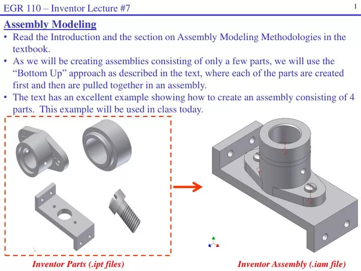
EGR 110 – Inventor Lecture #7 • Assembly Modeling • Read the Introduction and the section on Assembly Modeling Methodologies in the textbook. • As we will be creating assemblies consisting of only a few parts, we will use the “Bottom Up” approach as described in the text, where each of the parts are created first and then are pulled together in an assembly. • The text has an excellent example showing how to create an assembly consisting of 4 parts. This example will be used in class today. Inventor Parts (.ipt files) Inventor Assembly (.iam file)
EGR 110 – Inventor Lecture #7 • Example – Creating an Assembly (the entire presentation is based this example) • Create the Parts • Create the four parts required for the assembly as shown below. • Refer to the text for the dimensions. • The instructor may also decide to provide you with the part files. Base-Plate Cap-Screw Bearing Collar Downloading the parts for this example (two options): Download the parts from the course Blackboard site or Download the file Bearing.zip from the following web site and unzip (extract) it: http://faculty.tcc.edu/PGordy/EGR110/index.htm
EGR 110 – Inventor Lecture #7 • Create a new Assembly • Select File – New – Standard(in).iam - Create
EGR 110 – Inventor Lecture #7 • Select the Base Part • Each assembly will have a base part. • It is important to carefully select which part to serve as the base, although it is often an obvious choice. For example, you might choose the chassis of a car, the base of a lamp, the frame of a window, etc. • Other parts will later be added to the assembly. • Note that the base part will not be able to move (zero degrees of freedom) whereas other parts can be moved in several ways (to be described shortly). • Also note that the entire assembly will use the orientation and coordinate system of the base part, so selecting and designing the base part is important. Natural choice for the base part
EGR 110 – Inventor Lecture #7 • Place the Base Part • Select Place (or Place Component) from the Assembly Panel. • Browse and pick the desired part (Base-Plate ) to serve as a base and select Open. • Right-click and pick OK after inserting it as Inventor will otherwise let you insert multiple copies).
EGR 110 – Inventor Lecture #7 • Place the Second Component • Select Place Component again and select the bearing (bearing.ipt). • Place it somewhere near the base part.
EGR 110 – Inventor Lecture #7 • Degrees of Freedom • If the degrees of freedom symbol is not showing, turn it on by • selecting View – Degrees of Freedom. • In general, components have 6 degrees of freedom, meaning that they can be moved in the assembly as follows: • Moved (translated) in the x, y, or z direction • Rotated about the x, y, or z axis Pushpin indicates that the Base-Plate is fixed and has 0 degrees of freedom Degrees of Freedom Symbol
EGR 110 – Inventor Lecture #7 • Assembly Constraints • Parts are put together in assemblies by placing assembly constraints on the parts. • Each time a constraint is added, one or more degrees of freedom are eliminated. • Select Constrain from the Assembly Panel to place an assembly constraint. • The Place Constraint window will appear as shown below. • Note that four types of assembly constraints are available as shown below. • A description of each type of constraint is provided on the following slide. Angle Tangent Insert Mate Solution (illustration) for Mate constraint
EGR 110 – Inventor Lecture #7 Mate – Constrains features to be face-to-face or adjacent to one another. They can be in the same direction (flush) or in the opposite direction and they can be separated by an offset. Angle – Constrains features to be separated by a specified angle. Insert – Constrains circular features to share the same axis (become co-axial). The distance between the selected circular faces can be zero (the default) or given an offset value. Tangent – Constrains features such as faces, planes, cylinders, spheres, and cones to make contact at a point of tangency.
EGR 110 – Inventor Lecture #7 • Applying Constraints to the Second Component • Apply the Mate constraint. • Select the bottom face of the Bearing and the top face of the Base-Plate. • Note that now only three degrees of freedom are left and the Bearing can be slid along the surface of the Base-Plate and rotated along the vertical axis. • Try repeating the last operation (or edit the Mate constraint in the browser) and try different offsets. Return the offset to 0.0 when finished.
EGR 110 – Inventor Lecture #7 • Applying Constraints to the Second Component (continued) • Apply the Mate constraint a second time. • Select the center line of a small hole in the Bearing and the centerline of the corresponding small hole in the Base-Plate. • Note that now only one degree of freedom is left (rotation about one axis) and that you can drag the part to rotate it. • One more constraint is needed to fully constrain the part.
EGR 110 – Inventor Lecture #7 • Applying Constraints to the Second Component (continued) • Apply the Mate constraint a third time. • Select the center line of the other small hole (or the large hole) in the Bearing and the centerline of the corresponding hole in the Base-Plate. Note that there are other combinations of constraints that could have been used. There are often many ways to apply constraints. • Note that the Bearing now has zero degrees of freedom and cannot be moved.
EGR 110 – Inventor Lecture #7 • Applying Constraints to the Third Component • Select Place Component again and select the Collar part. Place it somewhere near the assembly. • Apply the Insert constraint. • Select two circular surfaces that are coaxial and will also mate (be touching). • Note that the collar now has one degree of freedom (rotation about its axis). • It is not necessary to eliminate the last degree of freedom (especially since this part would naturally be free to rotate if you built it.)
EGR 110 – Inventor Lecture #7 • Applying Constraints to the Third Component • Select Place Component again and select the Cap-Screw part. Place two screws somewhere near the assembly. • Apply the Insert constraint and insert the two screws into the desired holes (see final assembly below). Note that the screws are still free to rotate.
EGR 110 – Inventor Lecture #7 • Rotating Components • It is sometimes useful to rotate a component to make it easier to select a desired surface or feature. • To rotate a component, select the Rotate and then select the desired component. Note that the familiar cursors appear as are used with the Orbit command. Cursors used to rotate component
EGR 110 – Inventor Lecture #7 • Moving Components • Even when components are constrained in an assembly, they can be temporarily moved using the Move command. • It may be useful to move a component out of the way while you place another component. • Components can also be moved to make a simple “exploded view” of an assembly, although we will see a better way to do this later. • To move a component: • Select Move then select and drag the component to be moved. • Select Assemble to return the components to their constrained positions.
EGR 110 – Inventor Lecture #7 • Editing Parts used in Assemblies • Inventor will allow you to edit designs at any level, so you can easily modify a part while in an assembly. Try the following: • Right-click on Base-Plate in the browser and select Edit. • Right-click on Hole3 in the browser (or any of the holes not used with the Cap-Screws) and select Edit Feature. • Change the diameter of Hole3 from 0.5 to 0.75 inches. • Right-click in the graphics window and select Finish Edit to update the part. Change diameter of Hole3 Edit Base-Plate.ipt from the assembly Edit Hole3 Result: New hole size
EGR 110 – Inventor Lecture #7 • Creating an Assembly Drawing • Assembly drawings (idw files) are created in the same way they are created for parts. • Select File – New – Standard.idw • Change the sheet size to A-size (portrait). • Select Base to insert a base view. Select Top Right Isometric (if a different base view is automatically inserted, delete it first). • Change the scale to 0.75
EGR 110 – Inventor Lecture #7 • Adding a Parts List • Select Parts List from the Annotate menu • Select the file name for the assembly (Assembly2.iam in this example) • Select OK and then move the parts list that appears to the desire location (see next slide).
EGR 110 – Inventor Lecture #7 • Editing a Parts List • The Parts List below has 4 columns, but columns may be added or deleted with various properties for each part. • Right-click on the Parts List and select Edit Parts List to add or remove columns. This window appears after selecting Edit Parts List:
EGR 110 – Inventor Lecture #7 • Adding/Deleting Columns in a Parts List • Select Column Chooser and add columns for Mass and Material. Also remove the column for Description. Note that the material will appear as Default for each part. before Column Chooser after
EGR 110 – Inventor Lecture #7 • Parts List with modified columns
EGR 110 – Inventor Lecture #7 • Changing Material Type in a Part • Note that the Parts List will be updated if you make changes to the assembly. • Example - Change the material type for the Collar as follows: • Switch back to the assembly drawing (iam file). • Right-click on Collar in the browser and select Edit. • Right-click on Collar again in the browser and select iProperties. • Click on the Physical tab. • Change the material type to Copper, Alloy and then select OK. • Right-click in the graphics area and select Finish Edit. • Switch back to the drawing (idw) file and select Update (if • necessary) on the Quick Access Tool Bar. Update Material and mass changed
EGR 110 – Inventor Lecture #7 • Adding Balloons to the Assembly • Balloons are numbered labels inside circles with leaders that identify a part. • The numbers are generated automatically from the Parts List. • From the Annotate menu select Balloon • Pick a part (where the arrow will be attached), pick a point again to place a bend in the leader, and then right-click and pick Continue to finish the balloon and to add the next balloon. Right-click and pick Cancel (Esc)when finished.
EGR 110 – Inventor Lecture #7 • Final Assembly Drawing • Note that dimensions are not shown in the assembly drawing. • Detail drawings with dimensions are typically provided for each part in the assembly.