Download
1 / 70
700 likes | 809 Views
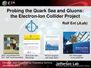
Probing the Quark Sea and Gluons: the Electron-Ion Collider Project. Rolf Ent ( JLab ). 2007 Long-Range Plan EIC: “half” recommendation. 2010 JLab User Workshops. EIC white paper – to be published. INT10-3 program >500 page report. Fermilab : Joint Experimental-Theoretical Seminar

E N D
Probing the Quark Sea and Gluons: the Electron-Ion Collider Project Rolf Ent (JLab) 2007 Long-Range Plan EIC: “half” recommendation 2010 JLab User Workshops EIC white paper – to be published INT10-3 program >500 page report Fermilab: Joint Experimental-Theoretical Seminar January 11, 2013
Probing the Quark Sea and Gluons: the Electron-Ion Collider Project • Electron-Ion Colliders Worldwide • Electron-Ion Collider Nuclear Science • Electron-Ion Collider Accelerator Design • Integrated Detector and Interaction Region • Electron-Ion Collider Status and Plans EIC is the generic name for the Nuclear Science-driven Electron-Ion Collider, presently considered in the US
Electron Ion Colliders on the World Map FAIR ENC RHIC eRHIC HIAF EIC@China CEBAF MEIC LHC LHeC HERA
Electron Ion Colliders Past Possible Future High-Energy Physics Nuclear Physics
EIC vsLHeC EIC: L = 1033-1034cm-2s-1 Ecm = 20-70+ GeV LHeC: L = 1.1x1033 cm-2s-1 Ecm = 1.4 TeV • Variable energy range • Polarized and heavy ion beams • High luminosity in energy region • of interest for nuclear science • Add 70-100 GeV electron ring to • interact with LHC ion beam • Use LHC-B interaction region • High luminosity mainly due to • large g’s (= E/m) of beams • Nuclear sciencegoals: • Map the spin and spatial structure of quarks and gluons in nucleons • Discover the collective effects of gluons in atomic nuclei • Understand the emergence of hadronic matter from color charge • High-Energy/Nuclear physics goals: • Parton dynamics at the TeVscale • - high-Q2 electron-quark scattering • (constrain the size of the quark) • - physics beyond the Standard Model • - physics of high partondensities (low x) high-energy e-p collider to follow on DESY, plus plans for e-A collider “world’s first polarized e-p collider and world’s first e-A collider”
A High-Luminosity US-Based Electron Ion Collider Stage I eRHIC @ BNL Stage I MEIC / ELIC @ JLab (MEIC) √s = 25 – 100GeV Ee = 3 – 10 GeV Ep = 50 – 250 GeV EPb = up to 100 GeV/A √s = 15 – 66 GeV Ee = 3 – 11 GeV Ep = 20 – 100 GeV EPb = up to 40 GeV/A (Hall A & C) CLAS12 ELIC MEIC eRHIC: take advantage of higher proton/ion energies eRHIC1 eRHIC2 MEIC: take advantage of lower proton/ion energies for detector/IR design “world’s first polarized e-p collider and world’s first e-A collider” Stage 1 MEIC: dedicated ~1 km ring optimized for 30-100 GeV protons
Into the “sea”: the EIC • With 12 GeV we study mostly the valence quark component • An EIC aims to study the sea quarks and gluon-dominated matter. MEIC EIC 12 GeV
The Structure of the Proton Naïve Quark Model: proton = uud (valence quarks) QCD: proton = uud + uu + dd + ss + … The proton sea has a non-trivial structure: u ≠ d & gluons are abundant The proton is far morethan just its up + up + down (valence) quark structure Nuclear physicists are trying to answer how basic properties like mass, shape, and spin come about from the flood of gluons, quark/anti-quark pairs, and a few ever-present quarks.
QCDand the Origin of Mass • 99% of the proton’s mass/energy is due to the self-generating gluon field • Higgs mechanism has no role here. • The similarity of mass between the proton and neutron arises from the fact that the gluon dynamics are the same • Quarks contribute almost nothing. M(up) + M(up) + M(down) ~ 10 MeV << M(proton)
The Physics Program of an EIC I) Map the spin and spatial structure of quarks and gluons in nucleons Sea quark and gluon polarization Transverse spatial distributions Orbital motion of quarks/gluons Parton correlations: beyond one-body densities (show the nucleon structure picture of the day…) II) Discover the collective effects of gluons in atomic nuclei Color transparency: Small-size configurations Nuclear gluons: EMC effect, shadowing Strong color fields: Unitarity limit, saturation Fluctuations: Diffraction (without gluons there are no protons, no neutrons, no atomic nuclei) III) Understand the emergence of hadronic matter from color charge Materialization of color: Fragmentation, hadron breakup, color correlations Parton propagation in matter: Radiation, energy loss (how does M = E/c2 work to create pions and nucleons?) Needs high luminosity and range of energies + some developing ideas for fundamental symmetry tests
Helicity PDFs at an EIC Q2 = 10 GeV2 current data 5 x 250 starts here w/ EIC data 5 x 100 starts here
Sea Quark Polarization • Spin-Flavor Decomposition of the Light Quark Sea } Needs intermediate √s ~ 30(and good luminosity) u u u Many models predict Du > 0, Dd < 0 > u d | p = + + + … u u u u d d d d
d3r TMD PDFs f1u(x,kT), .. h1u(x,kT) Unified View of Nucleon Structure 6D Dist. Wpu(x,kT,r) Wigner distributions d2kT drz GPDs/IPDs 3D imaging dx & Fourier Transformation d2kT d2rT Form Factors GE(Q2), GM(Q2) PDFs f1u(x), .. h1u(x) 1D
Towards Imaging - Two Approaches GPDs TMDs 2+1 D picture in momentum space 2+1 D picture in impact-parameter space 0.0 0.5 -0.5 0.5 ky 0.0 -0.5 kx bx [fm] (Lattice Calculation of the IP density of up quark, QCDSF/UKQCD Coll., 2006) Quark Siversfunction fit to SIDIS (Anselminoet al. 2009) • intrinsic transverse motion • spin-orbit correlations = indicator of OAM • non-trivial factorization • accessible in SIDIS, DY • collinear but long. momentum transfer • indicator of OAM; access to Ji’s total Jq,g • existing factorization proofs • DVCS, deep exclusive meson production
Transverse Quark & Gluon Imaging Deep exclusive measurements in ep/eA with an EIC: diffractive: transverse gluon imaging J/y, f, ro, g (DVCS) non-diffractive: quark spin/flavor structure p, K, r+, … Are gluons uniformly distributed in nuclear matter or are there small clumps of glue? Are gluons & various quark flavors similarly distributed? (some hints to the contrary) Describe correlation of longitudinal momentum and transverse position of quarks/gluons Transverse quark/gluon imaging of nucleon (“tomography”)
Detailed differential images from nucleon’s partonic structure EIC: Gluon size from J/Y and felectroproduction (Q2 > 10 GeV2) Hints from HERA: Area (q + q) > Area (g) Dynamical models predict difference: pion cloud, constituent quark picture - t [Transverse distribution derived directly from t dependence] t EIC: singlet quark size from deeply virtual compton scattering EIC: strange and non-strange (sea) quark size from p and K production • Q2 > 10 GeV2 • for factorization • Statistics hungry • at high Q2!
Example: Transverse Spatial Distribution of Gluons from J/Y DVCS transverse spatial projections in progress
Image the Transverse Momentum of the Quarks Swing to the left, swing to the right: A surprise of transverse-spin experiments The difference between the p+, p–, and K+ asymmetries reveals that quarks and anti-quarks of different flavor are orbiting in different ways within the proton. dsh ~ Seq2q(x) dsfDfh(z) Sivers distribution
Image the Transverse Momentum of the Quarks Only a small subset of the (x,Q2) landscape has been mapped here: terra incognita Gray band: present “knowledge” Purple band: EIC (2s) u u An EIC with good luminosity & high transverse polarization is the optimal tool to to study this!
Gluons in Nuclei What do we know about gluons in a nucleus? Ratio of gluons in lead to deuterium NOTHING!!! • EIC: access gluons through FL (needs variable energy) and dF2/dln(Q2) • Knowledge of gluon PDF essential for quantitative studies of onset of saturation
Tomography: Hard Diffraction Diffractive event No activity in proton direction A 7 TeV equivalent electron bombarding the proton … but nothing happens to the proton in 15% of cases • Predictions for eA for such hard diffractive events range up to: ~30-40%... given saturation models
Hadronization – parton propagation in matter L p+ e’ pT g* DpT2 = pT2(A) – pT2(2H) e “pT Broadening” Can we learn more from correlating with the target fragmentation region? • Comprehensive studies possible: • wide range of energy v = 10-1000 GeV • move hadronization inside/outside nucleus, • distinguish energy loss and attenuation • wide range of Q2: QCD evolution of • fragmentation functions and medium effects • Hadronization of charm, bottom • Clean probes with definite QCD predictions • High luminosity • Multi-dimensional binning and correlations • √s > 30: jets and their substructure in eA Accardi, Dupre DpT2 EIC: Understand the conversion of color charge to hadrons through fragmentation and breakup
To cover the physics we need… x = Q2/ys s Range in y s • For large or small y, uncertainties in kinematic variables become large • Detecting the electron ymax / ymin ~ 10 • Also detecting hadrons ymax / ymin ~ 100 • Requires hermetic detector (no holes) Range in s C. Weiss C. Weiss C. Weiss • Accelerator considerations limit smin • Depends on smax (dynamic range) pQCD radiation Vacuum fluct. Range of kinematics • At fixed s, changing the ratio Ee / Eion can for some reactions improve resolution, particle identification (PID), and acceptance radiative gluons/sea valence quarks/gluons non-pert. sea quarks/gluons Range of nuclei
A High-Luminosity US-Based Electron Ion Collider NSAC 2007 Long-Range Plan: “An Electron-Ion Collider (EIC)with polarized beams has been embraced by the U.S. nuclear science community as embodying the vision for reaching the next QCD frontier. EIC would provide unique capabilities for the study of QCD well beyond those available at existing facilities worldwide and complementary to those planned for the next generation of accelerators in Europe and Asia.” • Base EIC Requirements per Executive Summary of Institute for Nuclear Theory Report: • range in energies from √s ~ 20 to √s ~ 70 & variable • fully-polarized (>70%), longitudinal and transverse • ion species from deuteriumto A = 200 or so • high luminosity: about 1034e-nucleons cm-2 s-1 • multiple interaction regions • upgradable to higher energies (√s ~ 150 GeV) “world’s first polarized e-p collider and world’s first e-A collider”
How MEIC meets the Design Specs • Base EIC Requirements per Executive Summary INT Report: • center of mass energies from √s ~ 20 to √s ~ 70 GeV & variable • electron energies above 3 GeV to allow efficient electron trigger • proton energy adjustable to optimize particle identification • highly polarized (>70%) electron and nucleon beams • - longitudinally polarized electron and nucleon beams • - transversely polarized nucleon beams • ion species from deuterium to A = 200 or so • high luminosity ~1034 e-nucleons cm-2 s-1 • optimal luminosity in √s ~ 30-50 region • luminosity ≥1033 e-nucleons cm-2 s-1 in √s ~ 20-70 region • multiple interaction regions • integrated detector/interaction region • non-zero crossing angle of colliding beams • crossing in ion beam to prevent synchrotron background • - ion beam final focus quads at ~7 m to allow for full acceptance detector space • bore of ion beam final focus quads sufficient to let particles pass through • up to t ~ 2 GeV2 (t ~ Ep2Q2) • upgradeable to center of mass energy of about √150 GeV
MEIC (= stage-I EIC @ JLab) Design • Collider is based on a figure eight concept • Avoids crossing polarization resonances • Improves polarization for all species • Makes polarized deuterons possible • Advantage of having a new ion ring • Highest luminosity comes with final focus quadrupoles close together • Interferes with detection of (spectator) particles at small angles • MEIC is designed around a full-acceptance detector with ±7 meters free space around the interaction point and a high-luminosity detector with ±4.5 meters free space • The present MEIC design takes a conservative technical approach by limiting several key design parameters within state-of-the-art. It relies on regular electron coolingto obtain the ion beam properties. • The present JLab EIC design focuses on a CM energy range from 12 up to 65 GeV Emphasis on integrated detector/interaction region
EIC@JLab (MEIC) Technical Design Strategy Limit as many design parameters as we can to within or close tothe present state-of-art in order to minimize technical uncertainty and R&D tasks • Stored electron current should not be larger than 3 A • Stored proton/ion current should be less than 1 A (better below 0.5 A) • Maximum synchrotron radiation power density is 20 kW/m • Maximum peak field of warm electron magnet is 1.7 T • Maximum peak field of ion superconducting dipole magnet is 6 T • Maximum betatron value at FF quad is 2.5 km • New beta-star, appropriate to the detector requirements 2.5 km βmax + 7 m βy*= 2 cm Fullacceptance 2.5 km βmax + 4.5 m βy*=0.8 cm Large acceptance • This design will form a base for future optimization guided by • Evolution of the science program • Technology innovation and R&D advances
Medium Energy EIC@JLab Warm ion collider ring (up to 25 GeV) Cold ion collider ring (up to 100 GeV) Electron collider ring (3 to 11 GeV) • JLab Concept • Initial configuration (LEIC & MEIC): • 3-11 GeV on 10-25 & 20-100 GeVep/eAcollider • fully-polarized, longitudinal and transverse • luminosity: up to ~2 x 1034 e-nucleons cm-2s-1 • Upgradable to higher energies (EIC) • 3-11 GeV on up to 250 GeVep/eA collider • luminosity: up to few x 1034 e-nucleons cm-2 s-1 “Like Mike” “Ike”
MEIC Design Report • Posted: arXiv:1209.0757 • Stable concept for 3 years “… was impressed by the outstanding quality of the present MEIC design” “The report is an excellent integrated discussion of all aspects of the MEIC concept.” (JSA Science Council 08//29/12) Design Feature: High & Flexible Polarization Fully integrated detector/interaction region • EPJA article by JLab theory on EIC science case • EIC white paper near-final (w. BNL & JLab users)
Design Features: High Polarization All ion rings (two boosters, collider) have a figure-8 shape • Spin precessions in the left &right parts of the ring are exactly cancelled • Net spin precession (spin tune) is zero, thus energy independent • Ensures spin preservation and ease of spin manipulation • Avoids energy-dependent spin sensitivity for ion all species • The only practical way to accommodate medium energy polarized deuterons This design feature promises a high polarization for all light ion beams (The electron ring has a similar shape since it shares a tunnel with the ion ring, section 4.7) Use Siberian Snakes/solenoids to arrange polarization at IPs longitudinal axis Solenoid Vertical axis Proton or Helium-3 beams Deuteron beam Insertion Longitudinal polarization at both IPs Transverse polarization at both IPs Longitudinal polarization at one IP Transverse polarization at one IP Slide 30
Design Features: High Luminosity • Based on high bunch repetition rate CW colliding beams • Very high bunch repetition rate Very small bunch charge • Very short bunch length (sz ~ b*) Very small β* • Crab crossing Small transverse emittance • A proven concept: KEK-B @2x1034/cm2/s • JLab aims to replicate this in colliders w/ hadron beams • The electron beam from CEBAF possesses a high bunch repetition rate • Ion beams from a new ion complex to match the electron beam
A New Ion Complex at JLab cooling cooling to high energy collider ring ion sources SRF Linac pre-booster (accumulator ring) large booster medium energy collider ring Pre-booster (by NIU) Beam from LINAC Extraction to large booster ARC 1 Electron Cooling Collimation Injection Insertion section ARC 3 QWR QWR HWR DSR IH RFQ Ion Sources RF Cavities Stripper MEBT ARC 2 Solenoids Normal conducting Superconducting Ion Linac (by ANL)
MEIC Layout • Interaction point locations: • Downstream ends of the electron straight sections to reduce synchrotron radiation background • Upstream ends of the ion straight sections to reduce residual gas scattering background • Vertical stacking for identical ring circumferences • Horizontal crab crossing at IPs due to flat colliding beams • Ion beams execute vertical excursion to the plane of the electron orbit for enabling a horizontal crossing Ion path Interaction Regions Electron path Warm large booster (up to 25 GeV/c) Ion source Prebooster Ion transfer beam line Large Ion Booster Electron Collider Ion Collider SRF linac Cold 97 GeV/c proton collider ring Three Figure-8 rings stacked vertically Electron ring Medium energy IP with horizontal crab crossing Injector • Ring circumference: 1340 m • Maximum ring separation: 4 m • Figure-8 crossing angle: 60 deg. 12 GeV CEBAF
Crab Crossing High bunch repetition rate requires crab crossing of colliding beams to avoid parasitic beam-beam collisions Present baseline: 50 mrad crab crossing angle Crab cavity State-of-the-art: KEKB Squashed cell@TM110 Mode Vkick=1.4 MV, Esp= 21 MV/m 750 MHz SRF crab cavity design ongoing
Crab Crossing • Restore effective head-on bunch collisions with 50 mrad crossing angle Preserve luminosity • Dispersive crabbing (regular accelerating / bunching cavities in dispersive region) vs.Deflection crabbing (novel TEM-type SRF cavity at ODU/JLab, very promising!) Incoming At IP Outgoing
Electron Cooling • Essential to achieve high luminosity for MEIC • Traditional electron cooling, not Coherent Electron Cooling • MEIC cooling scheme Pre-booster: Cooling for assisting accumulation of positive ion beams (Using a low energy DC electron beam, existing technology) Collider ring: Initial cooling after injection Final coolingafter boost & re-bunching, for reaching design values Continuous coolingduring collision for suppressing IBS (Using new technologies) • Challenges in cooling at MEIC collider ring • High ion energy (State-of-the-art: Fermilab recycler, 8 GeV anti-proton, DC e-beam) • High current, high bunch repetition rate CW cooling electron beam
Staged Electron Cooling In Collider Ring • Initial cooling: after injection for reduction of longitudinal emittance < acceleration • Final cooling: after boost & rebunching, for reaching design values of beam parameters • Continuous cooling: during collision for suppressing IBS & preserving luminosity lifetime
ERL Circulator Electron Cooler solenoid • Design Choices • Energy Recovery Linac (ERL) • Compact circulator ring • to meet design challenges • Large RF power (up to 81 MW) • Long gun lifetime (average current 1.5 A) • Required technologies • High bunch charge magnetized gun • High current ERL (55 MeV, 15 to150 mA) • Ultra fast kicker 30 m Solenoid (20 m) ion bunch injector electron bunch energy recovery SRF Cooling section Fast kicker e-bunches circulates 10 -100 times reduction of current from an ERL by a same factor Fast kicker circulator ring dumper • Optimization • eliminating a long return path • could double the cooling rate Proposal: A technology demonstration using JLab FEL facility dump injector SRF Linac Slide 38
MEIC Collider Ring Footprint Universal Spin Rotator (8.8°/4.4°, 50 m) 1/4 Electron Arc (106.8°, 140 m) IR(125 m) IR(125 m) Universal Spin Rotator (8.8°/4.4°, 50 m) Experimental Hall (radius 15 m) RF (25 m) Figure-8 Crossing Angle: 2x30° Universal Spin Rotator (8.8°/4.4°, 50 m) Compton Polarimeter (28 m) 1/4 Electron Arc (106.8°, 140 m) 3rd IR (125 m) Universal Spin Rotator (8.8°/4.4°, 50 m) Injection from CEBAF • Ring design is a balance between • Synchrotron radiation prefers a large ring (arc) length • Ion space charge prefers a small ring circumference • Multiple IPs require long straight sections • Straights also hold required service components (cooling, injection and ejection, etc.)
MEIC assumptions x = Q2/ys s s (x,Q2) phase space directly correlated with s (=4EeEp) : @ Q2 = 1 lowest x scales like s-1 @ Q2 = 10 lowest x scales as 10s-1 • Detecting only the electron ymax / ymin ~ 10 • Also detecting all hadrons ymax / ymin ~ 100 C. Weiss C. Weiss (“Medium-Energy”) MEIC@JLaboption driven by: access to sea quarks (x > 0.01 (0.001?)or so) deep exclusive scattering at Q2 > 10 (?) any QCD machine needs range in Q2 s = few 100 - 1000 seems right ballpark s = few 1000 allows access to gluons, shadowing Requirements for deep exclusive and high-Q2 semi-inclusive reactions also drives request for (lower &) more symmetric beam energies. Requirements for very-forward angle detection folded in IR design
Where do particles go - general e p or A Token example: 1H(e,e’π+)n • Several processes in e-p: • “DIS” (electron-quark scattering) e + p e’ + X • “Semi-Inclusive DIS (SIDIS)” e + p e’ + meson + X • “Deep Exclusive Scattering (DES)”e + p e’ + photon/meson + baryon • Diffractive Scattering e + p e’ + p + X • Target fragmentation e + p e’ + many mesons + baryons • Even more processes in e-A: • “DIS” e + A e’ + X • “SIDIS” e + A e’ + meson + X • “Coherent DES” e + A e’ + photon/meson + nucleus • Diffractive Scattering e + A e’ + A + X • Target fragmentation e + A e’ + many mesons + baryons • Evaporation processes e + A e’ + A’ + neutrons In general, e-p and even more e-A colliders have a large fraction of their science related to the detection of what happens to the ion beams. The struck quark remnants can be guided to go to the central detector region with Q2 cuts, but the spectator quark or struck nucleus remnants will go in the forward (ion) direction.
Transverse spatial imaging – recoil baryons 40 mrad @ t = -1 GeV2 ep → e'π+n 8 mrad @ t = -1 5x30 GeV DVCS on the proton 5x250 GeV ~ √t/Ep J.H. Lee T. Horn • Colliders allow straightforward detection of recoil baryons, making it possible to map the t-distribution down to very low values of –t • eRHIC (partially) solves this by squeezing the high-energy recoil baryons through a high-gradient interaction region focusing magnet and the use of Roman Pots • At very high proton energies, recoil baryons are all scattered at small angles • Moderate proton energies give the best resolution • High luminosity at intermediate proton energies and excellent small-angle detection make the MEIC a perfect tool for imaging of the proton
Detector/IR in pocket formulas • Luminosity ~ 1/b* • bmax~ 2 km = l2/b*(l = distance IP to 1st quad) Example: l = 7 m, b* = 20 mm bmax = 2.5 km • IP divergence angle ~ 1/sqrt(b*) Example: l = 7 m, b* = 20 mm angle ~ 0.3 mr Example: 12 s beam-stay-clear area 12 x 0.3 mr = 3.6 mr ~ 0.2o • FFQ gradient ~ Ep,max/sqrt(b*)(for fixed bmax, magnet length) Example: 6.8 kG/cm for Q3 @ 12 m @ 60 GeV 7 T field for 10 cm (~0.5o) aperture Making b* too small complicates small-angle (~0.5o) detection before ion Final Focusing Quads, and would require too high a peak field for these quads given the large apertures (up to ~0.5o).b* = 1-2 cm and Ep = 20-100 GeV ballpark right!
MEIC:Fullacceptance detector – strategy 7 meters In general, e-p and even more e-A colliders have a large fraction of their science related to the detection of what happens to the ion beams… spectator quark or struck nucleus remnants will go in the forward (ion) directionthis drives the integrated detector/interaction region design: NO HOLES! central detector with endcaps small angle hadron detection ultra forward hadron detection n low-Q2 electron detection large aperture electron quads 60 mrad bend ion quads p small diameter electron quads e p 50 mrad beam (crab) crossing angle detectors solenoid ion FFQs ion dipole w/ detectors ions IP 0 mrad electrons electron FFQs 50 mrad Three-stage detection 2+3 m 2 m 2 m Central detector (P. Nadel-Turonski, V. Morozov, T. Horn, C. Hyde)
MEIC: FullAcceptance Detector 7 meters (P. Nadel-Turonski, V. Morozov, T. Horn, C. Hyde) detectors solenoid ion FFQs ion dipole w/ detectors ions IP 0 mrad electrons electron FFQs 50 mrad 2+3 m 2 m 2 m Three-stage detection Central detector TOF Detect particles with angles down to 0.5obefore ion FFQs. Need 1-2 Tm dipole Detect particles with angles below 0.5obeyond ion FFQs and in arcs. Need 4 m machine element free region Solenoid yoke + Muon Detector RICH or DIRC/LTCC Tracking RICH EM Calorimeter HTCC 4-5m Muon Detector Hadron Calorimeter EM Calorimeter Very-forward detector Large dipole bend @ 20 meter from IP (to correct 50 mr ion horizontal crossing angle) allows for very-small angle detection (<0.3o). Need 20 m machine element free region Solenoid yoke + Hadronic Calorimeter All incorporated in MEIC design 2m 3m 2m
MEIC Detector & Interaction Region GEANT4 model of extended IR exists • Neutron detection in a 25 mrad cone down to zero degrees • Excellent acceptance for all ion fragments • Recoil baryon acceptance: • up to 99.5% of beam energy for all angles • down to 2-3 mrad for all momenta • Momentum resolution < 3x10⁻⁴ • limited by intrinsic beam momentum spread Full acceptance • 100 GeV maximum ion energy allows using large-aperture magnets with achievable field strengths n p e n 20 Tm dipole p 2 Tm dipole solenoid e
Extended Detector & Interaction Region Truly fully integrated detector & interaction region, also for eA
Design Feature: Full-Acceptance Detector Forward acceptance horizontal plane Forward acceptance vertical plane Full acceptance detector • Demonstrated excellent acceptance & resolution • Completed the detector-optimized IR optics • Fully integrated detector and interaction region • Working on hardware engineering design Addressing accelerator challenges • Demonstrated chromaticity compensation (section 7.5) 6 T max 9 T max 12 T max
Reviews and Activities • 2nd EIC International Advisory Committee Review (Nov. 2-3, 2009) (Accelerator members: R. Gerig, U. Wienands) • Physics-Machine Joint Meeting (for a design goal) (Feb. 11&12, 2010) • MEIC Machine Design Week (March 4-8, 2010) (Detector/IR consultant: M. Sullivan of SLAC ) • MEIC Internal Machine Design Review (Sept. 15-16, 2010) (Reviewers: A. Chao and G. Hoffstaetter) • RF & Beam Synchronization Mini-Workshop (Oct. 29, 2010) • MEIC Ion Complex Design Workshop (Jan. 27-28, 2011) • 3rdElC International Advisory Committee Review (April 9, 2011) (Accelerator members: R. Gerig, S. Nagaitsev, V. Shiltsev) • MEIC Detector and IR Design Mini-Workshop (Oct. 31, 2011) • ERL Circulator Cooler Test Facility Retreat (Jan. 31, 2012)
EIC Progress • Close and frequent collaboration between accelerator and nuclear physicists regarding the machine, interaction region and detector requirements has taken place. • “We are proud to announce that we have achieved a fully integrated detector and interaction region” • Several JLab user proposals for generic detector R&D call • Draft MEIC Intermediate Design Report completed Aug. 2012 • Concept for regular electron cooling further worked out • Many aspects of cooling can be tested at JLab/FEL • Mainly use “brute force” lenient at lower energies • Cost Estimate developed, estimate being iterated • (3 main cost drivers: Ion Linac, SC Magnets & SRF Cooling, Civil construction) • Steering committee with many JLab users working on EIC white paper accessible to general nuclear science community • Integrate LEIC (up to 25 GeV/c protons) into design