Download
1 / 1
10 likes | 114 Views
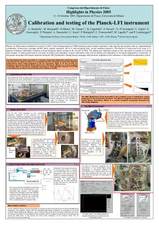
Cryofacility and test setup.

E N D
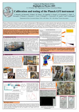
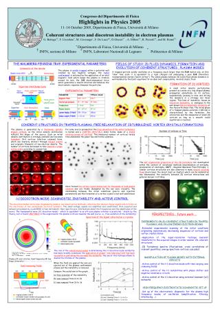
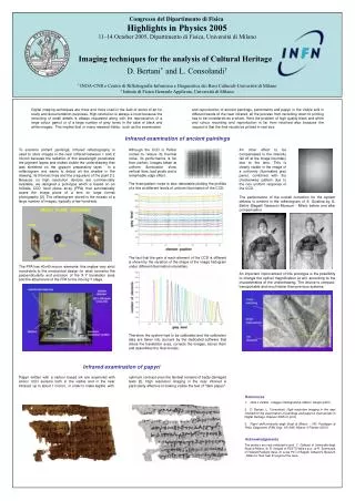
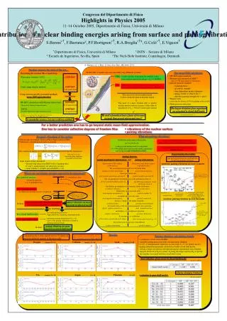
Cryofacility and test setup Each radiometer chain is tested under vacuum in a dedicated cryo-facility in order to reproduce a thermal environment as much representative as possible of the flight conditions. In particular the radiometer is cooled at 20 K in the front end and is maintained at room temperature at the back end. The 20 K front end and the 300 K back end are connected by waveguides that are thermally linked to three interfaces Waveguide supports at ~ 50 K, ~ 100 K and ~ 150 K, respectively. Finally the input loads are ECCOSORB loads cooled at ~ 4K. These temperatures are provided by three coolers, i.e. a 4 K cooler and two 20 K coolers. In the figure we show the cryo-facility workbench with the cold tips of the three coolers. All the thermal stages are actively regulated via PID controllers in order to maintain the temperature stability at the mK level. 20K cooler tips 4K cooler tip 20K plate Congresso del Dipartimento di Fisica Highlights in Physics 2005 11–14 October 2005, Dipartimento di Fisica, Università di Milano Calibration and testing of the Planck-LFI instrument A. Mennella*, M. Bersanelli*, D.Maino*, M. Tomasi*,†, B. Cappellini*, S. Pezzati*, O. D’Arcangelo‡, L. Figini‡, S. Garavaglia‡, P. Platania‡, A. Simonetto‡, C. Sozzi‡, P. Battaglia, C. Franceschet, M. Lapolla , and P. Leutenegger * Dipartimento di Fisica, Università di Milano, †INAF- IASF, Milano, ‡ IFP - CNR, Milano, Alcatel Alenia Spazio Planck, an ESA mission scheduled for launch in 2007, is the third generation of CMB anisotropy space mission planned to fully map the sky emission with an unprecedented combination of frequency coverage (30-857 GHz), angular resolution (30’ to 5’) and sensitivity (few K per resolution element). The Planck-LFI instrument is an array of 11 pseudo-correlation radiometric receivers in three frequency bands centred at 30, 44 and 70 GHz. The testing and calibration phase of this instrument is carried out in three main phases: (I) testing performed at unit level, (ii) testing and calibration of each radiometric chain and (iii) testing and verification of the whole integrated LFI instrument. In this poster we present the results obtained during the QM (Qualification Model) testing campaign with particular emphasis to the calibration of the individual radiometric chains. The RCA (Radiometer Chain Assembly) is a complete independent differential radiometric chain collecting the sky signal by means of a corrugated feed horn. Each RCA is tested and calibrated independently before being integrated in the LFI instrument. RCAs at 30 and 44 GHz are integrated and tested at Alcatel-Alenia Spazio S.p.A. (Vimodrone, Milano) in a custom designed cryofacility. RCAs at 70 GHz are integrated and tested at Ylinen (Helsinki, Finland). The LFI QM is constituted by one RCA at 30 and 44 GHz and by 2 RCAs at 70 GHz. The RAA (Radiometer Array Assembly) is the complete array of radiometric chains integrated in the mechanical structure. The RAA is integrated and tested in Alcatel Alenia Spazio (Vimodrone, Milan) in a custom designed cryofacility developed by CSL (Liegi, Belgium). The QM LFI instrument Details of the RCA Bipods Waveguides CAD 3D model of the LFI instrument. The feed-horns and the front-end modules of the radiometers are integrated into an aluminum structure (the main-frame) interfaced to the satellite by bipods. The waveguides carry the radiometric signal from the 20K front-end to the 300K back-end. Three radiative shields (so-called V-grooves) allow an effective dissipation into space of the heat coming from the warm stage. In the central part of the focal plane the feed-horns of the HFI instrument are visible The 44 GHz RCA integrated on the cryofacility workbench. Attached to the feed-horn an OMT (Orthomode Transducer) separates the incoming wave into two orthogonally polarised components. Each wave is amplified and compared with a stable signal from a ~4 K black body. Further RF amplification is provided at room temperature before detection. Waveguides follow a complex routing for mechanical integration purposes and are made by different materials to optimise thermal and radiometric performances. Below, in a close-up of the radiometer front-end, we show the OMT, the Front-end Module and the two waveguides that carry the reference signal from the reference loads to the front-end module. waveguides back-end module OMT Front-end unit Feed horn Back-end unit The input “sky” load, a black body custom-designed by IASF Bologna to provide and adapted input with < -30 dB return loss. The feed-horn faces an ECCOSORB bed through the hole visible in the figure. The flexible waveguide is used to inject a monochromatic signal in the swept source test (see below) The QM LFI instrument during integration in the Alcatel-Alenia Spazio laboratories in Vimodrone (Milano). The instrument is supported by a custom Ground Support Equipment that is removed once integrated in the cryofacility 4K reference loads A test in more detail: the swept source test waveguides The QM LFI instrument integrated into the cryochamber in the Alcatel-Alenia Spazio laboratories in Vimodrone (Milano). An ECCOSORB bed is placed below the focal plane and constitutes the “sky” load, i.e. the black body that provides the input signal to the radiometers. back-end unit (300K) Schematic of the swept source test. A monochromatic wave in injected into the RCA feed horn at various frequencies in the receiver band by means of a flexible waveguide. The radiometric output is recorded and the power is plotted against frequency. On the QM instrument the test has been run only with the 30 GHz radiometer front-end unit (20K) The receiver effective bandwidth is defined as: and depends on the characteristics of the radiometer gain function. The bandpass measured by the swept source test matched simulation results obtained with a numerical model of the LFI receivers. The measured effective bandwidths at 30 GHz were ~ 6 GHz, consistently with the required value. sky load (20K) Data analysis software An IDL software package has been developed to analyse the data produced during the RCA and RAA testing campaigns. The software, named LIFE (Lfi Integrated perFormace Evaluator) is constituted by two main modules: RaNA (Radiometer aNAlyser), used to analyse data produced by individual radiometers during the RCA tests, and LAMA (Lfi Array Measurements Analyser) used to analyse the data from the complete array during the RAA tests. In the figures we show some snapshots of the software. More info on http://lucifer.mi.iasf.cnr.it/web/rana The data viewer. This interface allows to navigate interactively into radiometric and housekeeping data. The RaNA and LAMA main windows