Download
1 / 53
550 likes | 723 Views
Nikhef Colloquium, 6 March 2009. KM3NeT – towards a km 3 -Scale Neutrino Telescope in the Mediterranean Sea. Uli Katz ECAP / Univ. Erlangen. Scientific rationale Neutrino telescopes KM3NeT: Towards design and construction Summary. ~E -2.7. knee 1 part m -2 yr -1. ~E -3. ~E -2.7.

E N D
Nikhef Colloquium, 6 March 2009 KM3NeT – towards a km3-Scale Neutrino Telescope in the Mediterranean Sea Uli Katz ECAP / Univ. Erlangen
Scientific rationale • Neutrino telescopes • KM3NeT: Towards design and construction • Summary
~E-2.7 knee 1 part m-2 yr-1 ~E-3 ~E-2.7 ankle 1 part km-2 yr-1 LHC The Mysterious Cosmic Rays • Particles impinging on Earth from outer space carry energies up to1021 eV(the kinetic energy of a tennis ball at ~200km/h.) • The acceleration mechanisms are unknown. • Cosmic rays carry a significant fraction of the energy of the universe – cosmologically relevant! • Neutrinos play a key role in studying the origin of cosmic rays.
Cosmic rays Cosmic rays • Cosmic ray acceleration yields neutrinos and gammas! • … but gammas also from purely leptonic processes Neutrino Production Mechanism • Neutrinos are produced in the interaction of high energy nucleons with matter or radiation: • Simultaneously, gamma production takes place:
protons E>1019 eV (few 10 Mpc) neutrinos gammas (0.01 - 10 Mpc) protons E<1019 eV Particle Propagation in the Universe Cosmic accelerator 1 parsec (pc) = 3.26 light years (ly) Photons: absorbed on dust and radiation; Protons/nuclei: deviated by magnetic fields, reactions with radiation (CMB)
Potential Galactic Sources • The candidate accelerators of cosmic rays • Supernova remnants • Pulsar wind nebulae • Micro-quasars • … • Interaction of cosmic rays with interstellar matter • Possibly strong n signal if CR spectrum harder in Galactic Centre than on Earth (supported by recent MILAGRO results) • Unknown sources – what are the H.E.S.S.”TeV gamma only” objects?
High-Energy g Sources in the Galactic Disk The H.E.S.S. galactic plane scan Status 2007: • 18 Pulsar wind nubulae • 7 Shell-type supernova remnants • 4 Binaries • 2 Diffuse • 21 Unknown (no identified counterpart)
Example: SNR RX J1713.7-3946(shell-type supernova remnant) H.E.S.S. : Eg=200 GeV – 40 TeV • Accelerationbeyond 100 TeV. • Power-law energyspectrum, index ~2.1–2.2. W. Hofmann, ICRC 2005 Example: n’s from Supernova Remnants • Spectrum points to hadron acceleration n flux ~ g flux • Typical n energies: few TeV
n Flux Predictions from g Measurements Vela X (PWN) • Kappes et al., • astro-ph 0607286 Note: hadronic nature of Vela X is not clear! measured-ray flux (H.E.S.S.) mean atmospheric neutrino flux(Volkova, 1980, Sov.J.Nucl.Phys., 31(6), 784) expected neutrino flux –in reach for KM3NeT 1 error bands include systematic errors (20% norm., 10% index & cut-off)
Another Case: SNR RXJ1713.7-3946 • Good candidate for hadronic acceleration. • Expected signal well related to measured g flux, but depends on energy cut-off. • Few events/year over similar back-ground (1km3). • KM3NeT sensitivity in the right ballpark!
Potential Extragalactic Sources • AGNs • Models are rather diverse and uncertain • The recent Auger results may provide an upper limit / a normalisation point at ultra-high energies • Note : Above some 100 TeV the neutrino telescope field of view is restricted downwards (n absorption), but starts to be significant upwards. • Gamma ray bursts • Unique signature: Coincidence with gamma observation in time and direction • Source stacking possible
Candidate Accelerators: Active Galactic Nuclei (AGNs) AGNs are amongst the most energeticphenomena in theuniverse.
Pierre Auger: First Hints at UHE Cosmic Ray Sources circles: CR events red: AGNs • Directional correlation between AGN positions and cosmic rays (E>1019.7eV, 27 events). • Interpretation requires care and patience.
Science Cases for Neutrino Telescopes • Astroparticle physics with neutrinos • “Point sources”: Galactic and extragalactic sources of high-energy neutrinos • The diffuse neutrino flux • Neutrinos from Dark Matter annihilation • Search for exotics • Magnetic monopoles • Nuclearites, strangelets, … • Neutrino cross sections at high(est) energies • Earth and marine sciences • Long-term, continuous measurements in deep-sea • Marine biology, oceanography, geology/geophysics, …
The Principle of Neutrino Telescopes Cherenkov light: • In water: θC≈ 43° • Spectral range used: ~ 350-500nm. Role of the Earth: • Screening against all particlesexcept neutrinos. • Atmosphere = target for productionof secondary neutrinos. Angular resolution in water: • Better than ~0.3° for neutrino energy above ~10 TeV, 0.1° at 100 TeV • Dominated by angle(n,m) below ~10 TeV (~0.6° at 1 TeV)
Neutrino Interaction Signatures • Neutrinos mainly from π-µ-e decays,roughly ne : nµ : nt = 1 : 2 : 0; • Arrival at Earth after oscillations:ne : nµ : nt≈ 1 : 1 : 1; • Key signature: muon tracksfromnµcharged current reactions(few 100m to several km long); • Electromagnetic/hadronic showers: “point sources” of Cherenkov light. muon track hadronic shower electromagn. shower hadronic shower hadronic shower
Muon Reconstructionn • The Cherenkov light is registered by the photomultipliers with nanosecond precision. • From time and position of the hits the direction of the muon can be reconstructed to some 0.1°. • Minimum requirement: 5 hits … in reality rather 10 hits. • Position calibration to ~10cm required (acoustic methods). 1.2 TeV muon traversing the detector.
The Neutrino Telescope World Map ANTARES, NEMO, NESTORjoined efforts to preparea km3-size neutrino telescope in the Mediterranean SeaKM3NeT NEMO
South Pole and Mediterranean Fields of View 2p downward sensitivity assumed In Mediterranean,visibilityof givensource canbe limitedto less than 24h per day > 25% > 75%
4800 Digital Optical modules on 80 strings 160 Ice-Cherenkov tank surface array (IceTop) Instrumenting 1 km3 of Antarctic Ice Surrounding exisiting AMANDA detector IceCube
IceCube 22: Point Source Search preliminary • Hottest spot found at right ascension 153º , declination 11º;pre-trial probability: 7×10⁻⁷ (4.8 sigma). • Accounting for trial factor, p-value is 1.34% (2.2 sigma). • At this significance level, consistent with fluctuation of background.
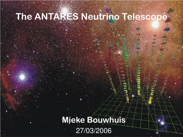
ANTARES: Detector Design • String-based detector; • Underwater connectionsby deep-sea submersible; • Downward-lookingphotomultipliers (PMs),axis at 45° to vertical; • 2500 m deep; • First deep-sea neutrino telescope in operation! 25 storeys, 348 m 14.5m 100 m Junction Box ~70 m
ANTARES Construction Milestones 2001 – 2003: • Main Electro-optical cable in 2001 • Junction Box in 2002 • Prototype Sector Line (PSL) & Mini Instrumentation Line (MIL) in 2003 2005 – April 2007: • Mini Instrumentation Line with OMs (MILOM) operated ~4 months in 2005 • Lines 1-5 running (connected between March 2006 and Jan. 2007) • Lines 6+7 deployed March/April 2007 • 2007 – now: • Deployment / connection of remaining lines completed in May 2008 • Replacement of MILOM by full instrumentation line (IL) • Physics with full detector !
ANTARES: Atmospheric Neutrinos down-going • 174 days of data with 9-12 lines • Reconstruction tuned for up-going tracks • Rate of neutrino candidates: ~ 3.5 events/day up-going Neutrino candidates M. Circella – Status of ANTARES VLVnT08 24
The NEMO Project • Extensive site exploration(Capo Passero near Catania, depth 3500 m); • R&D towards km3: architecture, mechanical structures, readout, electronics, cables ...; • Simulation. Example: Flexible tower • ~10 m bar length,bars 30-40 m apart; • 3 pairs of PMs per bar • Unfurls after deployment as compact structure.
NESTOR • Tower based detector(titanium structures). • Dry connections(recover − connect − redeploy). • Up- and downward looking PMs (15’’). • 4000-5200 m deep. • Test floor (reduced size) deployed & operated in 2003. • Deployment of 4 floors planned in 2009
NESTOR: the Delta-Berenike Platform • A dedicated deployment platform • In the final stage of construction • Can be important asset for KM3NeT deployment
KM3NeT: from the Idea to a Concept 11/2002 4/2008 2/2006 9/2006 9/2005 3/2004 First consultations of ANTARES, NEMO and NESTOR KM3NeT on ESFRI Roadmap The KM3NeT Conceptual Design Report Design Study proposal submitted KM3NeT on ESFRI List of Opportunities Begin of Design Study
Major Achievements to Date • Science & technology • Successful prototype deployments by NEMO and NESTOR • Installation and operation of ANTARES A large deep-sea neutrino telescope is feasible! • Politics & funding • Endorsement by ESFRI, ApPEC/ASPERA and ASTRONET • Funding through EU: Design Study, Preparatory Phase • Funding through national authorities:pilot projects, commitments for KM3NeT • Towards construction • Strong collaboration • Design concepts in CDR
The ESFRI Process • ESFRI = European Strategy Forum for Research Infrastructures • EU-initiated forum of research ministries and funding agencies. • Objective: Identify and support the priority research infrastructures in all fields of science. • Roadmap: Two editions with 35 (2006) and 43 (2008) RIs. • KM3NeT included in both editions.
The KM3NeT Conceptual Design Report • Presented to public atVLVnT0 workshop in Toulon, April 2008 • Summarises (a.o.) • Physics case • Generic requirements • Pilot projects • Site studies • Technical implementation • Development plan • Project implementation available on www.km3net.org
Configuration Studies • Various geometries and OM configurations have been studied • None is optimal for all energies and directions • Local coincidence requirement poses important constraints on OM pattern
The Reference Detector • Sensitivity studies with a common detector layout • Geometry: • 15 x 15 vertical detection units on rectangular grid,horizontal distances 95 m • each carries 37 OMs, vertical distances 15.5 m • each OM with21 3’’ PMTs Effective area of reference detector This is NOT the final KM3NeT design!
Point Source Sensitivity • Based on muon detection • Why factor ~3 more sensitive than IceCube? • larger photo-cathode area • better direction resolution • Study still needs refinements
Diffuse Fluxes • Assuming E-2neutrino energy spectrum • Only muonsstudied • Energy reconstruction not yet included
Dark Matter Sensitivity • Scan mSUGRAparameter spaceand calculateneutrino flux foreach point • Focus on pointscompatible withWMAP data • Detectability: • Blue: ANTARES • Green: KM3NeT • Red: None of them
KM3NeT Design Goals • Sensitivity to exceed IceCube by “substantial factor” • Core process: nm+N m+X at neutrino energies beyond 100 GeV • Lifetime > 10 years without major maintenance, construction and deployment < 4 years • Some technical specifications: • time resolution 2 ns • position of OMs to better than 40 cm accuracy • two-hit separation < 25 ns • false coincidences dominated by marine background • coincidence acceptance > 50% • PM dark rate < 20% of 40K rate
Technical implementation • Photo-sensors and optical modules • Data acquisition, information technology and electronics • Mechanical structures • Deep-sea infrastructure • Deployment • Calibration • Associated science infrastructure
Optical Modules: Standard or Directional • A standard optical module, as used in ANTARES • Typically a 10’’ PMT in a 17’’ glass sphere • A segmented anode and a mirror system allow for directional resolution • First prototypes produced
… or Many Small Photomultipliers … • Basic idea: Use ca. 30 small (3’’ or 3.5’’) PMTs in standard sphere • Advantages: • increased photocathode area • improved 1-vs-2 photo-electron separation better sensitivity to coincidences • directionality • Prototype arrangements under study
Quasar 370 (Baikal) … or Hybrid Solutions • Idea: Use high voltage (~20kV) and send photo electrons on scintillator;detect scintillator light with small standard PMT. • Advantages: • Very good photo-electron counting, high quantum eff. • large angular sensitivity possible • Prototype development in CERN/Photonis/CPPM collaboration
Photocathode News • New photocathode developments by two companies (Hamamatsu, Photonis) • Factor 2 in quantum efficiency factor 2 in effective photocathode area! • Major gain in neutrino telescope sensitivity expected Hamamatsu Photonis
Data Acquisition and Information Technology Optical Module: • Conversion of PM signal for transmission • “Standard” electronic components or passive electro-optical solutions • Local thresholds/requirements Vertical signal transmission: • Fibres or copper? • Critical: time calibration and synchronisation, reliability On shore: • Computer farm for online data filter • High-bandwidth connection to mass storage and data analysis facilities Transmission to shore: • All data to shore (GB/s) • No alternative to fibres
Deep-Sea Infrastructure NEMO junction box design: Major components: • main cable & power transmission • network of secondary cableswith junction boxes • connectors Design considerations: • cable selection likely to be driven by commercial availability • junction boxes: may be custom-designed, work ongoingin NEMO • connectors: expensive, reduce number and/or complexity • risk considerations (single-point failures etc.)
Deployment: on the Surface … • Deployment operations require ships or dedicatedplatforms. • Ships: Buy, charter or use ships of opportunity. • Platform: Delta-Berenike.
Commercially available ROVs: … and in the Deep Sea • Deep-sea submersibles are likely needed for • laying out the deep-sea cable network • making connections to detection units • possibly maintenance and surveillance • Remotely operated vehicles (ROVs) available for a wide range of activities at various depths • Use of autonomous undersea vehicles (AUVs) under study
Installations for Earth and Sea Sciences • Earth and sea sciencedevices will be installed at variousdistances around theneutrino telescope • Issues: • interfaces • operation withoutmutual interference • stability of operationand data sharing • Synergy effects
The Candidate Sites • Locations of thethree pilot projects: • ANTARES: Toulon • NEMO: Capo Passero • NESTOR: Pylos • Long-term sitecharacterisationmeasurementsperformed and ongoing • Site decision requires scientific, technologicaland political input
Site Characterisation: an Example Important parameter: water transparency(absorption and scattering) Capo Passero Pylos (460 nm) Also: optical background, sea currents, sedimentation, biofouling, radioactivity, …
A Green Power Concept for KM3NeT • Idea: Use wind and/or solar power at KM3NeT shore installations toproduce the required electrical power. • Requires investment of 4-5 M€. • Can only work if coupled to a larger (public) power network.