Download
1 / 28
280 likes | 406 Views
This comprehensive guide explores the differences between real and virtual images, detailing their formation, orientation (inverted vs. upright), and size variations. It outlines the principles of reflection, including diffuse and regular reflection, as well as the characteristics of plane and curved mirrors, including concave and convex types. Additionally, it covers the concepts of refraction, optical density, and total internal reflection, explaining their applications in technology like fiber optics. Ideal for students and enthusiasts of optics, this guide provides essential insights into how light behaves in different media.

E N D
TYPE OF IMAGE • Real vs Virtual • Real Images can be seen on a piece of paper or screen placed because the focal point is in front of the mirror or behind the lens. • Virtual Images can not be seen on a piece of paper or screen, because the focal point is behind the mirror or in front of the lens. Virtual images are images which are formed in locations where light does not actually reach; it only appears to an observer as though the light were coming from this position.
ORIENTATION OF IMAGE • Inverted vs Upright • Inverted images are upside-down. • Upright images are right-side up.
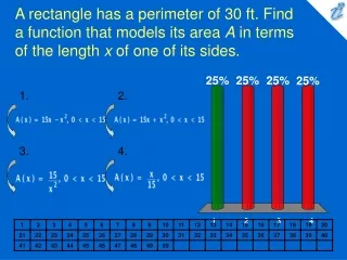
SIZE OF IMAGE • Smaller, Larger, or Same Size • Smaller Images are reduced in size compared to the actual object. • Larger Images are enlarged in size compared to the actual object. • Same Size Objects are unchanged in size compared to the actual object. • Size is also discussed quantitatively in terms of Magnification.
Reflection Light follows the same law of reflection as all other waves. Both angles are measured from the normal to the surface at the point of incidence. Glare- bright light that reflects to your eyes from the surface of smooth objects The angle of incidence is equal to the angle of reflection.
Diffuse vs Regular Reflection • Diffuse reflection is produced when the rays are reflected in many different directions by an uneven surface. • Regular reflection is produced by a very smooth, flat surface. The rays leave the surface parallel to each other.
Plane Mirrors • uniformly flat. The image is sent back virtual, erect, same size, and laterally inverted. • The image of the object looks like it is the same distance in back of the mirror as the actual object is in front of the mirror.
Types of Curved Mirrors • Concave (CONVERGENT) • focus the light at a point in front of the mirror. • reflect light from the inner surface. • Convex (DIVERGENT) • spread the light out. • reflect light from the outer surface.
Features of Curved Mirrors • Principal Axis: the straight line perpendicular to the surface of the mirror at its center. • Focal Point: the location where the parallel rays of light from the source meet, or converge. • Focal Length: the distance from the Focal Point to the mirror along the Principal Axis. • Center of Curvature: twice the distance of the focal point to the mirror surface. • Vertex: point where principal axis meets mirror
The image formed is dependent upon where the object is located relative to the focal point of the concave mirror.
3 rules • Incident ray parallel to P.A will reflect through focus • Incident ray through focus will reflect parallel to P.A. • Incident ray through Center of Curv. will reflect back on self • Don’t forget regular incidence=reflection from vertex
Locate an image • Use at least 2 lines through object • Image found where • Reflected lines cross • Virtual extensions of virtual lines (behind mirror) cross
Refraction The change in direction or bending of light at the boundary between two media. Refraction only occurs when the angle of incidence is non-zero.
Optical Density • The optical density of a material relates to the sluggish tendency of the atoms of a material to maintain the absorbed energy of an electromagnetic wave. • The more optically dense which a material is, the slower that a wave will move through the material.
Refraction From less dense to more dense: light travels more slowly and the angle of refraction is smaller than the angle of incidence. FST = Fast to Slow, Towards Normal From more dense to less dense: light travels more quickly and the angle of refraction is greater than the angle of incidence. SFA = Slow to Fast, Away From Normal
Two Criteria for Total Internal Reflection (T.I.R.) 1. Light must pass from a more optically dense to less optically dense medium. 2. There are only specific angles of incidence, called the critical angle, which is different for each medium.
An Application of T.I.R. Fiber optics. Telephone, radio,video, and television signals can now be sent with light beams rather than electric currents.This is more energy-efficient.
Why are different colors separated? • The shorter the wavelength, the more the light slows down when entering a new medium. • Violet has the shortest wavelength, so it slows down the most and bends the most.
Why are skies blue? • The two most common types of matter present in the atmosphere are gaseous nitrogen and oxygen. • These are most effective in scattering the higher frequency portions of the visible light spectrum • violet light is scattered most easily, followed by blue light, green light, etc
White light (ROYGBIV) passes through our atmosphere • High frequencies (BIV) become scattered by atmospheric particles • Lower frequencies (ROY) are most likely to pass through the atmosphere without a significant alteration in their direction • the skies are illuminated with light on the BIV end of the visible spectrum. • Thus, we view the skies as being blue in color.
Why Are Sunsets Red? • As the sun approaches the horizon line, sunlight must traverse a greater distance through our atmosphere; this is demonstrated in the diagram.
As the path which sunlight takes through our atmosphere increases in length, ROYGBIV encounters more and more atmospheric particles. • There is greater and greater amounts of yellow light scattered, leaving concentrations of red and orange frequencies of light. • Thus, sunsets have a reddish-orange hue. • The more particles in the atmosphere (clouds, pollution, etc.), the more pronounced the effect of a red sunset.