Download
1 / 25
250 likes | 445 Views
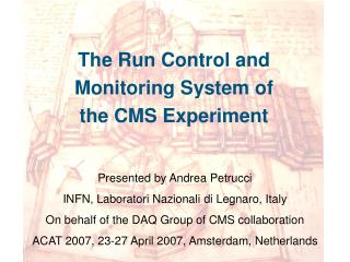
Run Control and Monitor System for the CMS Experiment Michele Gulmini CERN/EP – INFN Legnaro On behalf of the CMS DAQ collaboration CHEP 2003, San Diego USA, March 2003. Outline. R un C ontrol and M onitor S ystem : RCMS RCMS Architecture Session Managers Subsystem Controllers

E N D
Run Control and Monitor System for the CMS Experiment Michele Gulmini CERN/EP – INFN Legnaro On behalf of the CMS DAQ collaboration CHEP 2003, San Diego USA, March 2003
Outline Run Control and Monitor System : RCMS • RCMS Architecture • Session Managers • Subsystem Controllers • Services • RCMS Prototypes • RCMS for Small DAQ Systems • RCMS Demonstrators • Performance and Scalability Tests • Plans • Summary
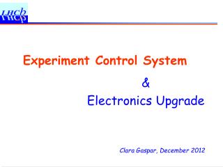
Trigger UI Event Builder Internet Intranet Event Filter RCMS RCMS UI UI DCS Computing Services UI RCMS Context Run Control and Monitor System • The Run Control and Monitor System (RCMS) is the collection of hardware and software components responsible for controlling and monitoring the CMS experiment during the data taking. • RCMS enables users to access and control the experiment from any part in the world providing a “virtual counting room”, where physicists and operators can effectively taking shifts from a distance. • RCMS views the experiment as a set of partitions, where a partition is a grouping of entities that can be operated independently. • Main operations are configuration, monitoring, error handling, logging and synchronization with other subsystems.
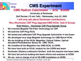
EVB Ctrl RU-B Ctrl FED-B Ctrl DCS Sub- System CS Sub- System RU Builder Sub-System FED Builder Sub-System Partitions Example UI UI UI UI UI UI Services Session Manager-B Session Manager-A Services Services Connection TRG Ctrl CS Ctrl DCS Ctrl EVF Ctrl Mu Cal Glbl EVB Sub-System EVF Sub-System TRG Sub-System
RCMS Logical Layout • The execution of the RCMS is organized on the basis of “Sessions”. • A Session is the allocation of the hardware and software of a CMS partition needed to perform data-taking. • Multiple Sessions may coexist and operate concurrently • Each Session is associated with a Session Manager (SMR), that coordinates all the actions
Sub-System Controller (SSC) • A SSC consists of a Function Manager (FM) and a local database (DB) service. • There is one FM per partition that receives requests from a Session Manager (SMR) and transforms them into the corresponding requests for actions that are sent to the sub-system. • The local DB service can be used as a proxy to the services.
Basic RCMS Services • SECURITY SERVICE • login and user account management; • RESOURCE SERVICE (RS) • informationabout DAQ resources and partitions; • INFORMATIONAND MONITOR SERVICE (IMS) • Collects messages and monitor data; distributes them to the subscribers; • JOB CONTROL • Starts, monitors and stops the software elements of RCMS, including the DAQ components • PROBLEM SOLVER • Uses information from the RS and IMS to identify mulfunctions and attempts to provide automatic recovery procedures where applicable
SS UserDB RS ConfDB IMS UI LogDB UI Services Connection Session Manager UI Job Ctrl PS SSC RCMS Resource Service Block Diagram • The Resource Service (RS) handles all the hardware and software components of the DAQ system including its partitions.
Information and Monitor Service Block Diagram SS UserDB RS ConfDB IMS UI LogDB UI Services Connection Session Manager UI Job Ctrl PS • The Information and Monitor Service (IMS) collects the information (log, warning, errors, monitoring, etc.) from the sub-systems and provides them to the subscribers. SSC RCMS
Time Requirements • Configuration and setup of the system: minutes • Control (state change, execution of commands): seconds • Monitoring: depending on the amount of data required Information and Monitor Service: • Tens of subscribers • Peak: about 2000 messages (status change, log) • Average: Tens to a few hundred messages/s
RCMS Prototypes • RCMS for small DAQ Systems • Fully functional RCMS systems targeted to small DAQs (Production systems, Testbeam DAQ systems) • Real-life examples used to check the RCMS functionality. • RCMS demonstrators • Partially functional RCMS systems targeted to prove scalability issues. • Test bed systems used to emulate slices or parts of the hierarchical structure of the final DAQ. • Help to confirm the architecture and to evaluate and eventually select the technologies to be used in the final system.
RCMS for small DAQs • Current Running Prototype: • Designed to work together with XDAQ CMS online software framework (XDAQ: See Chep2003 J. Gutleber talk - “Using XDAQ in Application Scenarios of the CMS Experiment”) • Available services: • Resource Service (RS) • Information and Monitor Service (IMS) • SubSystem Controllers (Function Managers) • Session Managers • GUIs • Technologies and tools: • Java Servlets (Apache Tomcat) • Sun “Java Web Services Developer Package” (JWSDP) • JAXP, JAXM, XPath, ... • SOAP communication protocol • Databases • XMLDB interface • eXist native XML database • mySQL
RCMS for Small DAQs – Current Applications • CMS Muon Drift Tubes • Chamber Production DAQ (Legnaro - Italy) • Testbeam (CERN – next May) • CMS Tracker • “ROD System Tests” (CERN) • Testbeam (CERN – next May) • CMS TriDAS (CERN) • DAQ Column • TDR Demonstrator
F S M XML definition Java Implementation SM/FM servlet Session and Function Manager Prototype SS UserDB RS ConfDB IMS UI LogDB UI Services Connection Session Manager UI Job Ctrl PS • Function Managers and Session Manager have a built in Finite State Machine (FSM) to command the controlled components, and to track their state; • The FSM is composed of a XML definition and a Java class implementation representing the actions to be performed; • The definition and the implementation of the FSMs are managed by the Resource Service; • Session Manager and Function Managers are launched when a new “Session” is opened, and can have a hierarchical structure; SSC RCMS
RS and IMS Prototype Resource Service XML Parser Java client SOAP Servlet container (TOMCAT) XML Parser (CASTOR) XMLDB Interface XML Parser XML:DB C++ client XML Java Objs REL DB Java Servlet IMS Tomcat servlet container Soap XML message Xpath Filter Engine JAXM Java Publisher PUBLISH JAXM JDOM FS XOAP XDAQ Application Subs Info XMLDB DB (eXist, File,mySQL) SUBSCRIBE Tomcat/ Jetty NOTIFY JAXM Java Subscriber
RCMS GUIs • Generic GUI: • Insertion and retrieval of resources (PCs, software, partitions, etc.) • Ability to command, set and retrieve parameters from XDAQ applications • Scripting facility • Customisation facilities (plugins) • Muon DT TestBeam GUI
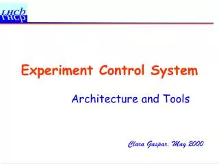
RCMS Demonstrators Legnaro T2 CMS farm: 136 P3 1-1.2 GHz processors
SOAP PC PC FM FM XDAQ XDAQ XDAQ XDAQ XDAQ XDAQ ..... ..... Demonstrator 1 • Exploring the ability to command a set of XDAQ executives running “empty” applications • The time measured represents the time required to perform a state change of the entire cluster FM: Function Manager PC PC FM FM .....
120 nodes 100 ms Demonstrator 1
Demonstrator 2 • Simplified version of a log message service based on Web Services technologies (Glue platform) • 15 clients and a variable number of Web Services used • The performance scales linearly with the number of instances of the service available
DB mySQL IMS IMS IMS IMS Prototype Test (I) PUBLISH Publisher • Percistency on eXist XML native DB not plotted – very slow • Between 200 and 300 SOAP messages/s handled by the IMS prototype
IMS IMS IMS IMS IMS IMS IMS IMS Prototype Test (2) NOTIFY PUBLISH Subscriber Publisher SUBSCRIBE • Performance improves augmenting the number of service instances • Notification mechanism not optimized • Test to be completed SOAP DB mySQL
XDAQ XDAQ XDAQ XDAQ IMS IMS proxy IMS proxy ..... ..... IMS hierarchical structure • Performance test done with the present prototypes: • Commanding a cluster of DAQ application fits the requirements • Information and Monitor Service prototype needs further investigation • Notification architecture • Hierarchical structure IMS hierarchical structure:
Future – OGSA??? • RCMS architecture is service and web oriented • Web services development tools (Apache Axis, Glue) may help to deploy reliable services quickly • Open Grid Service Architecture (OGSA) (http://www.globus.org/ogsa) is Web Services based • An alpha release of the framework is now available • First official release foreseen in a few months time • OGSA could be adopted for the RCMS services, providing several advantages: • RCMS open to the Grid world • Well supported and reliable framework • Useful built-in services • OGSA is under evaluation: • The RCMS Resource Service has been successfully ported (Globus 3.0 alpha release) • functionality and performance tests in progress
Summary and Plans • RCMS architecture defined • Prototypes developed aiming: • Control of small DAQs to be used in Testbeam applications: • Next May Testbeams (CMS Tracker and Muon DT) will provide important feedbacks on its functionality • Demonstrators aiming the validation of the architecture in terms of performance and scalability • Further investigation needed mainly on the IMS • Open Grid Software Architecture (OGSA) under evaluation • Problem Solver development in progress: • Error detection and recovery • Databases studies and evaluation foreseen