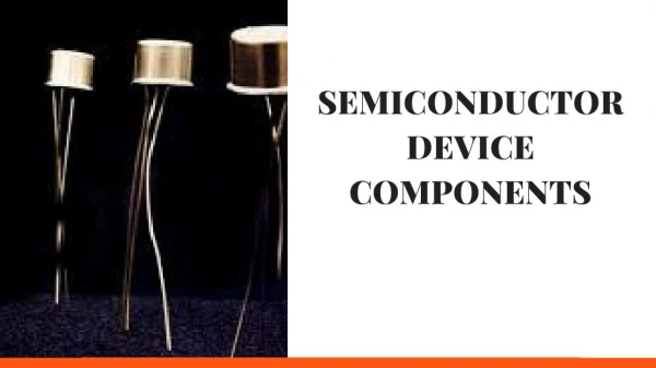
Semiconductor Basics
Semiconductor Basics. Chapter 1 . Atomic Structure. Elements are made of atoms 110 Elements; each has an atomic structure Today, quarks and leptons, and their antiparticles, are candidates for being the fundamental building blocks from which all else is made! Bohr Model

Semiconductor Basics
E N D
Presentation Transcript
Semiconductor Basics Chapter 1
Atomic Structure • Elements are made of atoms • 110 Elements; each has an atomic structure • Today, quarks and leptons, and their antiparticles, are candidates for being the fundamental building blocks from which all else is made! • Bohr Model • Atoms have planetary structure • Atoms are made of nucleus (Protons (+) & Neutrons) and electrons (-) 110 th element is called Darmstadtium (Ds)
Atomic Structure • Atoms go around the nucleolus in their orbits – discrete distances • Each orbit has some energy level • The closer the orbit to the nucleus the less energy it has • Group of orbits called shell • Electrons on the same shell have similar energy level • Valence shell is the outmost shell • Valence shell has valence electrons ready to be freed • Number of electrons (Ne) on each shell (n) • First shell has 2 electrons • Second shell has 8 electrons (not shown here) Ne = 2n2
Valence Shell • Atoms are made of valence shell and core • Core includes nucleus and other inner shells • For a Carbon atom the atomic number is 6 • Core charge = 6 P + 2 e = (+6)+(-2)=(+4) • Remember the first shell has 2 electrons
Elements • Basic categories • Conductors • Examples: Copper, silver • One valence electron , the e can easily be freed • Insulators • Valence electrons are tightly bounded to the atom • Semiconductors • Silicon, germanium (single element) • Gallium arsenide, indium phosphide (compounds) • They can act as conductors or insulators Free electrons Always free electrons Conduction band is where the electron leaves the valence shell and becomes free Valence band is where the outmost shell is
Semiconductors • Remember the further away from the nucleus the less energy is required to free the electrons • Germanium is less stable • Less energy is required to make the electron to jump to the conduction band • When atoms combine to form a solid, they arrange themselves in a symmetrical patterns • Semiconductor atoms (silicon) form crystals • Intrinsic crystals have no impurities
Conduction Electrons and Holes • Electrons exist only within prescribed energy bands • These bands are separated by energy gaps • When an electron jumps to the conduction band it causes a hole • When electron falls back to its initial valence recombination occurs • Consequently there are two different types of currents • Hole current (electrons are the minority carriers) • Electron current (holes are the minority carriers) Remember: We are interested in electrical current!
Doping • By adding impurities to the intrinsic semiconductor we can change the conductivity of the material – this is called doping • N-type doping • P-type doping • N-type: pentavalent (atom with 5 valence electrons) impurity atoms are added • [Sb(Antimony) + Si] • Negative charges (electrons) are generated • N-type has lots of free electrons • P-type: trivalent (atom with 3 valence electrons) impurity atoms are added • [B(Boron) + Si] • Positive charges (holes) are generated • P-type has lots of holes
Diodes • N region has lots of free electrons • P region has lots of holes • At equilibrium: total number positive and negative charges is the same (@ room temp) • At the pn junction the electrons and holes with different charges form an electric field • In order to move electrons through the electric field (generate current) we need some force (voltage) • This potential difference is called barrier voltage • When enough voltage is applied such that electrons are moved then we are biasing the diode • Two layers of positive and negative charges for depletion region – the region near the pn-junction is depleted of charge carriers)
Cathode n region Anode p region Biasing Types of a Diode • Forward bias • Bias voltage VBias > barrier voltage VBar • Reduction in + and – ions smaller depletion region • VBar Depends on material, doping, temp, etc. (e.g., for silicon it is 0.7 V) • Reverse bias • Essentially a condition that prevents electrons to pass through the diode • Very small reverse break down current • Larger depletion region is generated Connected to the negative side of the battery Connected to the positive side of the battery A K
Cathode n region Anode p region Biasing Types of a Diode (Forward) Small dynamic resistance Conventional Current Flow I (Forward) Moving electrons VBias A K Conventional Current Flow p n
Cathode n region Anode p region Biasing Types of a Diode (Reverse) Large resistance Instant pull of electrons Very Small Moving Electrons: Reverse Current) VBias Holes are left behind; large depletion region A K Conventional Current Flow p n
I-V Characteristic of a Diode Electrons moving from n to p region • Forward bias: current passes through • The knee is where VBias=VBar • At point B VBias < VBar Very little current • Note that at the knee the current increases rapidly but V(forward) stays almost the same • Reveres bias: No current passes through • When VBias < VBar Very little current (mu or nano Amp) • At the knee, the reverse current increases rapidly but the reverse voltage remains almost the same • Large reverse current can result in overheating and possibly damaging the diode (V=50V or higher typically) • Overheating results from high-speed electrons in the p-region knocking out electrons of atoms in n-region from their orbit to the conduction band • Hence, we use limiting resistors
Modeling a Diode (Forward Biasing) Use r’d (internal resistance) - Not linear!
Complete Modeling of a Diode Note that IF is the actual direction of electron current Forward bias: VBias = VF + IF(RLIMIT+rd); rd is typically given, VF typically is 0.7 V Reverse bias: VBias = VR + IR * RLIMIT; IR is typically given VR VF Showing the Actual electron direction
Example Find the current through the diode and the voltage across the resistor. Assume rd = 10 ohm Biasing? VF Forward biased Forward bias: VBias = VF + IF(RLIMIT+rd) 10 = 0.7 + IF(RLIMIT+10) IF=9.21 mA VF=0.7+IF*rd = 792 mV VRLIMIT = IF * RLIMIT = 9.21V
Example Find the current through the diode and the voltage across the resistor. Assume IR = I uA Note: Reverse biased VR Reverse bias: VBias = VR + IR * RLIMIT VRLIMIT = IR*VRLI MIT = 1mA VR=VBIAS-VRLIMIT=4.999 V
Forward Bias Calculate the voltage across the resistor.
Reverse Bias Calculate the voltage across the resistor.
Do this example on your own: i1 Make sure you can calculate and find all currents- Hint: find Vn, first Vn i3 i2 Vn Access this file from my web page