Download

1 / 21
210 likes | 338 Views
Channel Flow Routing. Reading: Applied Hydrology Sections 8.4, 9.1-9.4, 9.7. Brushy Creek Watershed. Reservoir Routing. Dam 7. Subasin Rainfall -Runoff. Subbasin BUT_060. Reach SBR_080 Downstream of Dam 7. How do we route the flow through Reach SBR_080?. Wedge storage in reach.

E N D
Channel Flow Routing Reading: Applied Hydrology Sections 8.4, 9.1-9.4, 9.7
Brushy Creek Watershed Reservoir Routing Dam 7 Subasin Rainfall -Runoff Subbasin BUT_060
Reach SBR_080 Downstream of Dam 7 How do we route the flow through Reach SBR_080?
Wedge storage in reach Advancing Flood Wave I > Q Receding Flood Wave Q > I Hydrologic river routing (Muskingum Method) K = travel time of peak through the reach X = weight on inflow versus outflow (0 ≤ X ≤ 0.5) X = 0 Reservoir, storage depends on outflow, no wedge X = 0.0 - 0.3 Natural stream
Muskingum Method (Cont.) Recall: Combine: If I(t), K and X are known, Q(t) can be calculated using above equations
Muskingum - Example • Given: • Inflow hydrograph • K = 2.3 hr, X = 0.15, Dt = 1 hour, Initial Q = 85 cfs • Find: • Outflow hydrograph using Muskingum routing method
Muskingum – Example (Cont.) C1 = 0.0631, C2 = 0.3442, C3 = 0.5927
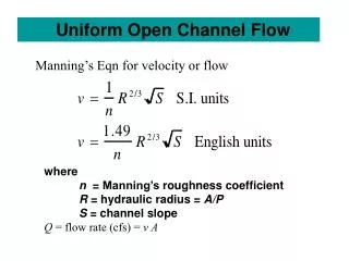
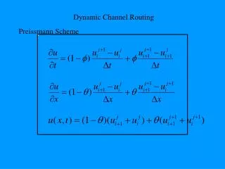
Unsteady Flow Routing in Open Channels • Flow is one-dimensional • Hydrostatic pressure prevails and vertical accelerations are negligible • Streamline curvature is small. • Bottom slope of the channel is small. • Manning’s equation is used to describe resistance effects • The fluid is incompressible
Continuity Equation Q = inflow to the control volume q = lateral inflow Rate of change of flow with distance Outflow from the C.V. Change in mass Elevation View Reynolds transport theorem Plan View
Momentum Equation • From Newton’s 2nd Law: • Net force = time rate of change of momentum Sum of forces on the C.V. Momentum stored within the C.V Momentum flow across the C. S.
Forces acting on the C.V. • Fg = Gravity force due to weight of water in the C.V. • Ff = friction force due to shear stress along the bottom and sides of the C.V. • Fe = contraction/expansion force due to abrupt changes in the channel cross-section • Fw = wind shear force due to frictional resistance of wind at the water surface • Fp = unbalanced pressure forces due to hydrostatic forces on the left and right hand side of the C.V. and pressure force exerted by banks Elevation View Plan View
Momentum Equation Sum of forces on the C.V. Momentum stored within the C.V Momentum flow across the C. S.
Momentum Equation(2) Local acceleration term Convective acceleration term Pressure force term Gravity force term Friction force term Kinematic Wave Diffusion Wave Dynamic Wave
Momentum Equation (3) Steady, uniform flow Steady, non-uniform flow Unsteady, non-uniform flow
Applications of different forms of momentum equation • Kinematic wave: when gravity forces and friction forces balance each other (steep slope channels with no back water effects) • Diffusion wave: when pressure forces are important in addition to gravity and frictional forces • Dynamic wave: when both inertial and pressure forces are important and backwater effects are not negligible (mild slope channels with downstream control, backwater effects)
Kinematic Wave • Kinematic wave celerity, ck is the speed of movement of the mass of a flood wave downstream • Approximately, ck = 5v/3 where v = water velocity
Muskingum-Cunge Method • A variant of the Muskingum method that has a more physical hydraulic basis • This is what Dean Djokic has used in the Brushy Creek HEC-HMS models • , where Δx = reach length or an increment of this length • , where B = surface width, S0 is the bed slope
Reach SBR_080 Downstream of Dam 7 How do we route the flow through Reach SBR_080?
Longitudinal profile for reach SBR_080 1545 ft 0.0008 1