OPEN CHANNEL FLOW
OPEN CHANNEL FLOW. The main concepts. Liquid flow with free surface at atmospheric pressure is called open channel flow. . Chezy formula is the main tool for hydraulic computations of open channel flow.

OPEN CHANNEL FLOW
E N D
Presentation Transcript
OPEN CHANNEL FLOW The main concepts
Liquid flow with free surface at atmospheric pressure is called open channel flow.
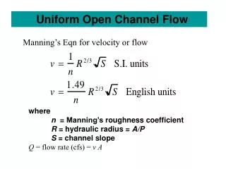
Chezy formula is the main tool for hydraulic computations of open channel flow. • Chezy coefficient usually is computed by Maning formula , where friction coefficient n is selected according to type and state of flow bed. • friction coefficient nis selected according to type and state of flow bed. For regular uniform cross section artificial channel in good conditions nis accosted within limits 0.0225 – 0.0275. Artificial channel in poor conditions it may be selected from therange 0.0275 – 0.0350, for natural river – 0.050 – 0.150.
For pipes of round cross section , = D2/4 andR= A/= D/4. Substituting R by D/4 Chezy formula may be rewritten in such shape • If this expression of hf is compared with Darcy – Weisbach formula Friction factor expresses resistanceChezy coefficient – conveyance of the channel. Thus physical senses and C are reversal, what confirm relationship
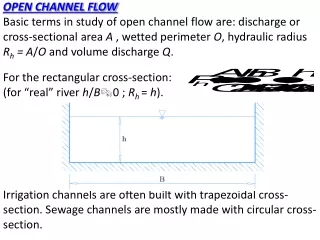
B Fig. 6.2 Geometric parameters of trapezoidal cross section m m h b B Fig. 6.1 The main geometrical parameters of open flow cross section h A Expression of parameters A, , Rof open channel are rather complex, even for the simplest case of trapezoidal cross section (Fig. 6.2):
1 H 2 h1 H2 h2 z Fig. 6.3 Parameters of open flow longitudinal profile H2 z1 L 1 z2 2 0 0 • A=bh+mh2 ; =b+2h; R=A/; B=b+2mh. Herem is slope coefficient, accepted from properties of ground forming the channel. • Longitudinal profile parameters include hydraulic gradient I=H/L and bottom slope i=Z/L, where H and Z are drop ofhydrodynamic head and bottom altitude on L length reach (Fig. 6.3)
1 H 2 h1 H2 h2 z Fig. 6.3 Parameters of open flow longitudinal profile H2 z1 L 1 z2 2 0 0 • Velocity at which bed of a channel is not eroded jet, but exceeding of which scour of bed starts, is called permissible non-scouring velocity. It depends on type of ground forming bed and slopes of a channel and varies within limits 0.30 m/s for fine sand to 1,90 m/s for rough gravel and boulders. • Permissible non-scouring velocity may be increased by lining of bottom and slopes of a channel. Lining by concrete pates on layer of gravel increases ability of channel to resist scour up to velocities (2.0 – 2.5) m/s. • Channels are designed for uniform water flow with constant water depth along it h1 = h2. For such regime of flow hydraulic gradient I = H/L corresponds to bottom slope i = z/L (Fig. 6.3).
Usual channel design problems may be divided into such groups: • - selection of cross section parametersm, b, h; • - computation of longitudinal slope; • - computation of velocity v; • - computation of flow rate Q. • Flow rate Q, permissible velocities vmin, vmax, longitudinal slope I to be known for selection of m, b, h. Slope coefficient m depends on ground mechanical properties and lining type, if such isapplied.
Energy of flow cross-section • Open water flow contains definite mechanical energy,expressed in relative units of length. Energy of flow crosssection may be characterized in Bernulli equation terms • If the energy is recorded with respect of data plane 0-0 at the level of the lowest point of cross section, point z is taken on free surface (Fig. 6.4), where z = h and p = 0,the expression of energy obtains such shape
A A B h h hc 0 0 0 0 Emin E Fig. 6.4 Open flow cross section energy-depth relationship
Substitutingv by Q/A the energy may be rewritten • It is evident from expression of the energyE, that increasing h leads to increment of the first part ofEexpression and decrement of the next part of it. At h = 0E = as well as at h = . • The energy E obtains minimal magnitude at definite magnitude of h corresponding
From this condition equalizing derivative to zero leads to But , what allows to rewrite as • Equation expreses minimal energy Emin condition • Depth corresponding minimal energy hc is called critical depth • The field of depth his divided into two parts h < hc and h > hc, which are called supercritical and subcritical flow states.
A A B h h hc 0 0 0 0 Emin E Fig. 6.4 Open flow cross section energy-depth relationship • Subcritical state may be recognized from and smooth freesurface of the flow. • Supercritical flow has wavy free surface and stormy motion of water. • Each energy magnitudeE > Emin corresponds two different depth h1 < hc and h2 < hc. • Thus, state of flow may be recognized comparing h with hc. Critical depthhcin general may be determined constructing relationship curve. Point of it corresponding allows to read hc.
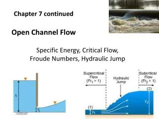
For the case of rectangular cross section B = b and A = bh., what allows to solve with respect to hc and to receive formula for direct computation of critical depth • Let us ratio Q/A substitute by v, ratio denote byha and name as average flow depth. Transformed ratio • is called Froude number, which is used to recognize state of open flow: when Fr < 1 flow is subcritical; when Fr = 1 – critical; when Fr > 1 flow is supercritical.
b a c Fig. 6.5 Hydraulic jump at gates (a), spillway (b), reach with h<hc (c) • Phenomenon of open flow change from supercritical to subcrcitical by forming stormy vortex is called hydraulic jump. It happens often at flow under gate, or downstream at spill way, also in the end of reach with water depth smaller than critical (see Fig. 6.5).