Download
1 / 26
280 likes | 449 Views
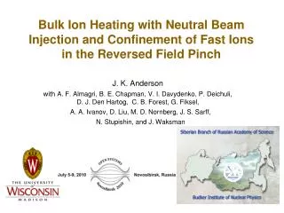
Bulk Ion Heating with Neutral Beam Injection and Confinement of Fast Ions in the Reversed Field Pinch. J. K. Anderson with A. F. Almagri, B. E. Chapman, V. I. Davydenko, P. Deichuli, D. J. Den Hartog, C. B. Forest, G. Fiksel, A. A. Ivanov, D. Liu, M. D. Nornberg, J. S. Sarff,

E N D
Bulk Ion Heating with Neutral Beam Injection and Confinement of Fast Ions in the Reversed Field Pinch • J. K. Anderson • with A. F. Almagri, B. E. Chapman, V. I. Davydenko, P. Deichuli, D. J. Den Hartog, C. B. Forest, G. Fiksel, • A. A. Ivanov, D. Liu, M. D. Nornberg, J. S. Sarff, • N. Stupishin, and J. Waksman Siberian Branch of Russian Academy of Science Budker Institute of Nuclear Physics
Outline • The Reversed Field Pinch (RFP) magnetic geometry • Not an Open System, • Unique parameter space to consider fast ion physics-- weak, strongly sheared B field • Neutral beam injection in the Madison Symmetric Torus (MST) • Fast ions confined much better than bulk plasma • Majority ion (deuterium) heating observed during NBI • First measurements: data presented without complete explanation. • Upcoming experiments with more diagnostics planned • Summary
RFP magnetic geometry Magnetic field maximum at geometric center Tangential NBI sources fast ions in region of peak magnetic field
RFP magnetic geometry: magnetized particles quickly lost Considering magnetic perturbations, field lines at core stochastically wander to boundary te ~ 1msec
NBI is significant factor in MST discharge NBI pulse: 20 msec, MST pulse: ~70 msec NBI power: 1 MW (25 kV, 40A) MST ohmic input: ~4-10 MW NBI electron source negligible NBI fuel doped with 3% D2; fusion neutrons some measure of fast ion density Approximate calibration: peak neutron flux ~ 1.5x10¹⁰ s-1 Flux decays after beam turn off
Classical fast ion slowing down time electrons 82% ions 15% impurities 3% ne =1013 cm-3 Te = 400 eV Efi= 25 keV For MST-like parameters Used to estimate fast ion confinement time
Fast ion confinement estimated by neutron decay Infinite fast ion confinement: neutron flux decays due to classical slowing of fast ions Actual neutron decay rate is faster due to finite loss rate of fast ions tfi >> te
Good fast ion confinement is understood Fast ion guiding center rotational transform deviates from magnetic transform Overlapping magnetic islands (br ) rapid electron transport Non-overlapping islands in fast ion transform (vr ) regions of good confinement
Fast ion confinement increases with confining field Counter-injection: poor fast ion confinement. Co-injection: tfi increases as B2 tfi slight increase with ne Magnetic field scanned by varying plasma current; Te increases ~ linearly with |B|
Classical transport modeling predicts fast ion density Tokamak transport code shows strongly peaked profile. Ramp-up and decay consistent with observed fast ion confinement Fast ion density ~15% of local bulk ion density Appreciable heating of e- and ions expected. Ion heating measured.
Bulk ion temperature measured by Rutherford Scattering NBI No NBI 16.6 keV He beam injected vertically into plasma. Scatters from D+; energy spectral width determines Ti Not perfectly symmetric gaussian; instrument broadening signficant. Tail effect of fast H+? Ti ~ 220eV Ti ~ 180eV
Ion temperature heats rapidly, cools quickly. He beam: 4ms pulse 40 eV DTi within 5 msec of turn-on DTi flat vs t until beam turn-off DTi decays quickly, 1.5 msec timescale.
Simulation of DTidoes not reproduce measured features Overall temperature change can be increased by assuming higher energy confinement or more localized heating. Higher confinement leads to longer ramp-up and decay times.
Simulation of DTidoes not reproduce measured features X X Overall temperature change can be increased by assuming higher energy confinement or more localized heating. Higher confinement leads to longer ramp-up and decay times. X X Recall approximate data
Summary • Initial results of 1 MW NBI into RFP presented • Fast ions confined much better than background plasma • Confinement time increases with confining field, ~ B2 • Thermal background ions heated during NBI beyond expectations • Core temperature change 2-4 times larger than simple calculation • Time scale on which heating occurs too fast • Further exciting experiments planned for campaign July-September 2010 • MST will make use of 3 neutral beams • NBI and 2 diagnostic beams for bulk and impurity ion temperature • Evolution of electron temperature (critical for quantitative comparison) to be measured • Compact neutral particle analyzer with up to 30keV range to be installed • Development of fast Ha diagnostic to measure fast ion dynamics • NBI into RFP high confinement mode: te increased by factor of 10, Te > 1keV
Fast Ion Da Diagnostic for NBI can utilize DNB Measurement of nfi profile very important Rutherford Scattering Some FIDA systems use fast-ion CX with neutrals from the same beam. Signal (small) is on top of large background from beam emission. CX with DNB neutrals will put a several nm red shift on signal carrying photons Doppler shift likely to be obscured by high shear on ~vertical views. Net red shift expected on toroidal viewing chords
Decay of rate of Ti slightly faster than decay rate of neutrons
Co-injected fast ions have very low prompt losses inboard outboard lost lost confined Ip=400kA, E=25keV counter Exit Pitch co Entry • MST favors co-injection. Even near wall born ions are well confined.
Global (0-d) modeling predicts measureable effects 0-D prediction for enhanced confinement discharge Te(0) ~800 eV; t ~ 10ms Classical collisions notable increase in Te with time Fast ion pressure significant fraction of bulk plasma pressure. Profile peaking can lead to local fast ion b > bulk b Injection into high b discharges may expose b limiting physics; pellet- fueled shots already exceed Mercier Momentum, current and beta all follow lower time trace
All collision rates are classical Fast ion confinement Fast ion energy losses 0-D modeling of fast ions energy and momentum exchangewith plasma (similar equation for momentum) Fast ion particle sources and losses Plasma electrons heating Plasma ions heating
Beam Geometry: Tangential injection shine-thru detector Launch at midplane not possible on MST; starting slightly above midplane with -6 degree angle– maximize beam deposition
Beam composition: 86% in fundamental 86% E ~2% E/18 10% E/2; 2% E/3
Beam divergence: at distance 2.1m, r = 67mm Measured beam radius acceptable: total distance traversed in MST = 2.8 m