Download
1 / 26
260 likes | 363 Views
U nified M A terials R esponse C O de (UMARCO) update & Thermal Response of Dendrites. Qiyang Hu (UCLA) Aaron Oyama (UCLA) Shahram Sharafat (UCLA) Jake Blanchard (Wisc) Nasr Ghoniem (UCLA). 19 th HAPL Meeting University of Wisconsin, Madison Oct. 22-23, 2008. Unified Simulation.

E N D
Unified MAterialsResponse COde (UMARCO) update& Thermal Response of Dendrites Qiyang Hu (UCLA) Aaron Oyama (UCLA) Shahram Sharafat (UCLA) Jake Blanchard (Wisc) Nasr Ghoniem (UCLA) 19th HAPL Meeting University of Wisconsin, Madison Oct. 22-23, 2008
Unified Simulation • Unified Model would • Avoid inconsistencies • Simplify modeling of wide variety of situations • New tool will model: • Heating profile (x-rays and ions) • Transient temperatures, stresses, strains • Fracture mechanics • Ion deposition profile, diffusion, and clustering
2 1 UMACRO Fortran’90 C++ HAPL pellet spectrum Material: Mech Prop. Material: SRIM Vol. Heating Rate Ion Implant. Profile Constitutive Lawelastic, plastic Temperature Coupled Diffusion Module:Ion, Helium, Bubbles, Carbon Transient stress strain field Module Stress WavesCoupled Fracture Module Improved
Modeling of Surface Cracking • Stress intensity factor decreases as cracks grow further from surface • Crack growth will arrest • Crack arrest will be more shallow for short pulse experiments (like RHEPP) UW
Crack Arrays • What if we have an array of cracks? • This will tend to relieve the stresses h TOFE 2008
Results for Crack Arrays KIC 7 MPa·m1/2 for recrystal W (A.V. Babak, 1981)
Reproducing HEROS • User defined f(t,y) • f(t,y) = react + diff + drift • reaction + drift term: • 13(18) variables: Alhajji-Sharafat-Ghoniem • 13+2 (temperature & carbon) • Test Results: • Single shot case: • UNC, UWM, ITER: OK! • Diffusion behavior is more obvious. • Multiple shot case: • 2 shots of “const temperature” HAPL case: OK! • Non-const temperature: • Linear from 400 C to 2000 C: OK!
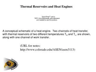
Solving thermal stress wave problem • Thermal wave stress governing equations: • System specifications: Q’’’ Stress-free& adiabatic Stress-free& temperature const. 20 ~ 200 Grids 10 m 3mm
Numerical considerations • 3 ODE equations: • A proper cvode option tested by bubble diffusion: • Solver: Krylov solver SPGMR • Precondition: CVBANDPRE module • Activate stability limit detection • Spatial finite-difference scheme:
Heating Rate (Q’’’) in HAPL • Ion implantation: ~0.1sec per step The most severe case:
Quasi-static Decomposition • Stress wave propagation time: • Thermal diffusion time scale: • Decomposition Fast (high frequency) Slow (quasi-static)
High-Frequency Thermo-elastic Waves forSelected Heating Step (duration 0.11sec)
Roughening or Dendrite • Roughening aims at minimizing energies (surface strain & stress) • Ultimately results in NANO- or MICRO-CASTELLATION • Why not start with a micro-castellated surface, similar to the UW-Madison Coral structure • Or simply start with Dendrites: • No surface stress or strains on dendrite surface
Dendrite Thermal Response to HAPL Threat HAPL Threat for 10.5 m radius chamber: Tip Radius: 1.5 mm
Dendrite Thermal Response to HAPL Threat Max Tip Temperature = 3836 °C at 4063 ns (end of shot) D=0 95.71 mm Max Base Temperature = 1308 °C at 120 μs after shot D D=95.71
Effect of Tip Radius on Temperature Transient Profile r=1 mm r=3 mm r=5 mm 95.71 mm
Summary & Conclusions • UMARCO (C++) framework completed • Fatigue of Interface Between W/Fe is a Concern. • Tungsten dendrite structure can be fabricated with various aspect ratios and tip radii • A tip radius of 5 mm will prevent tip melting • Mechanical modeling to be done, however stress and strains should remain fairly low because of dendrite geometry • Sputtering modeling including re-deposition shows minimal overall loss of material (see Tim Knowles’s poster).
Sputtering & RedepositionFor Dense Needle Configuration • Carbon velvet carpets have been used in space applications for ion thruster wall, with encouraging sputtering results after years of operation • Sputtering plus Redeposition modeling shows little loss of geometry (see next viewgraph).
Using CVODE SUite of Nonlinear and DIfferential/Algebraic equation Solversby Alan C. Hindmarsh and Radu Serban Direct: Krylov: Scaled Preconditioned Generalized Minimal Residual method