Download

1 / 45
530 likes | 778 Views
Applications of Vacuum Technology in the NIF Laser System. John Hitchcock Pete Biltoft LLNL. UCRL-PRES-219314. Agenda. National Ignition Facility (NIF) missions Overview of the NIF Movies Description of N Vacuum Systems Target Chamber Spatial Filters Plasma Electrode Pockels Cell

E N D
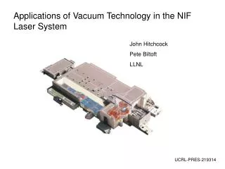
Applications of Vacuum Technology in the NIF Laser System John Hitchcock Pete Biltoft LLNL UCRL-PRES-219314
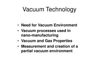
Agenda • National Ignition Facility (NIF) missions • Overview of the NIF • Movies • Description of N Vacuum Systems • Target Chamber • Spatial Filters • Plasma Electrode Pockels Cell • Diagnostic Vacuum Systems • Summary
Missions: The NIF laser system is being built to support important national security and research activities • Stockpile stewardship • Development of laser fusion as an energy source • Astrophysics Use any search engine & search for “NIF”.
The NIF laser would not be possible without the ready availability of stock and custom vacuum hardware • Vacuum pumps • Roughing & high vacuum (turbos, cryos) • Vacuum gauges • Hot and cold cathode ion gauges, rough vacuum gauges, capacitance manometers • Valves • Large 36” electro pneumatic gate valves to KF-25 manual valves • Feedthroughs • Electrical, mechanical and fluid
The NIF target chamber routinely achieves a pressure of < 5 x 10⁻⁶ Torr using a combination of roughing pumps, turbo pumps and cryo pumps
The NIF target chamber contains ports for beamlines, laser diagnostics, vacuum pumps and gauges
Alignment of the target is accomplished with a precision system called TASPOS
View inside NIF target chamber showing target positioner and workers on manlift inside the vessel
One quad of optics in the final optics assembly as seen from inside the target chamber. Stainless steel first wall panels surround the optics
Installation of the final optics assemblies onto the NIF target chamber required skilled workers following stringent cleanliness protocols
The target positioning system (TASPOS) includes a vacuum vessel with flexible track inside.
Lower hemisphere of NIF target chamber showing final optics assemblies installed
Target positioning system vacuum vessel during installation onto the NIF target chamber
NIF spatial filters require one of the largest clean-room rated vacuum systems in the world • 2300 tons of vessels • 10–5 torr vacuum • MIL STD 1246C level 100 — A/10 cleanliness CSF End Vessel (2x) TSF End Vessel (2x) 23.5m 60 m TSF Beam Tubes CSF Center Vessel TSF Center Vessel
Transport spatial filter vessels being installed. These vessels are evacuated to a pressure of ~ 5 x 10⁻⁵ Torr using turbo pumps
The transport spatial filter vessels occupy a significant portion of each of the two laser bays
Upper hemisphere of NIF target chamber showing beamlines and final optics assemblies
Prototype of the Plasma Electrode Pockels Cell (PEPC) line replaceable unit (LRU) during testing
PEPC during mock assembly (note aluminum surrogates for optics)
PEPC line replaceable unit on precision optical alignment fixture
PEPC line replaceable unit on precision optical alignment fixture
Utilities including foreline vacuum pump line supporting the Plasma electrode Pockels cell enter the LRU from the interface flange
Summary: The NIF laser system would not be possible without the technology and hardware provided by vacuum equipment manufacturers Some of the specific components of the NIF laser that rely on vacuum equipment include: • Vacuum relay telescopes in the preamplifier modules • Spatial filters • Amplifier flashlamps • Plasma Electrode Pockels Cell • Final Optics Assembly • Target chamber and target diagnostics • Precision Diagnostic System
Implosions conducted on NIF will be compared with computational models to optimize fusion experiments
The first attempt at fusion will be made in 2010 using the indirect drive fusion process
All 192 beams of the NIF laser will be focused onto a very small target
The target assembly for direct drive is held at 19 K +/- a few mK using a two-stage GM cryo-cooler similar to those developed for cryo pumps
In~ 2012 the NIF laser will be reconfigured for direct drive fusion
The NIF beamline contains several key elements that rely upon creation of stable vacuum environments
As a laser pulse moves through the NIF beamline it passes through a variety of optics and environments
The lasing media for the NIF main amplifiers is neodymium-doped glass. Vacuum chucks are used to lift and position these slabs into LRUs
Power lines that support operation of the main amplifier flashlamps. Each of the ~7000 flashlamp tubes is ~ 6 feet long and has an internal static vacuum. Flashlamps are expected to last > 20,000 shots.