ABR Traffic Management Specs
ABR Traffic Management Specs. Raj Jain Professor of CIS The Ohio State University Columbus, OH 43210-1277 Jain@ACM.Org http://www.cse.ohio-state.edu/~jain/. Overview. Overview. Overview. Overview. Forward and Backward RM cells In-Rate and Out-of-rate RM cells RM Cell Format

ABR Traffic Management Specs
E N D
Presentation Transcript
ABR Traffic Management Specs Raj JainProfessor of CISThe Ohio State UniversityColumbus, OH 43210-1277Jain@ACM.Org http://www.cse.ohio-state.edu/~jain/
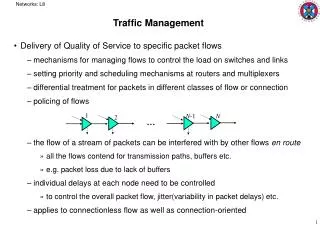
Overview Overview Overview Overview • Forward and Backward RM cells • In-Rate and Out-of-rate RM cells • RM Cell Format • Source behavior
Parameters • PCR: Peak Cell Rate • MCR: Minimum Cell Rate • ICR: Initial Cell Rate • RIF: Rate Increase Factor. ACR = ACR+RIF*PCR • Nrm: Number of cells per RM cell. Nrm-1 data + 1 RM • Mrm: Minimum # of cells per RM. Fixed at 2. • RDF: Rate decrease factor. ACR = ACR(1-RDF) • ACR: Allowed Cell Rate • CRM: Missing RM Cell count • ADTF: ACR Decrease Time Factor (Maximum idle time) • Trm: Maximum time between RM cells
Parameters (cont) • FRTT: Fixed Round-trip time • TBE: Transient buffer exposure. Maximum number of cells that can be sent before first RM cell returns. • CDF: Cutoff decrease factor.If no RM cell is received after Crm RM cells have been sentACR = ACR(1-CDF) • TCR: Tagged cell rate. Fixed at 10 c/s.Maximum rate at which a switch can generate BECNsor a source/destination can generate out-of-rate RM cells.
In-Rate and Out-of-Rate RM Cells • In-Rate: • Cells counted in the user’s rate • Can send as many as allowed by source rules • Have CLP = 0 • Out-of-Rate: • Not counted in the user’s rate • No more than 10 cells per VC per second • Have CLP = 1 Can be discarded by the network • Not Optional: The only way to get out of ACR=0 • ABR data cells can’t have CLP =1.
Forward and Backward RM Cells • Unidirectional: FRM Switch Source Destination BRM • Bidirectional: BRM FRM Switch Node 1 Node 2 FRM BRM
RM Cell Format 5 Bytes ATM Header 1 Byte 1 = ABR Protocol ID 1 bit 0 = Forward Direction 1 bit 1 = Switch/dest generated Backward Notification 1 bit 1 = High Congestion Congestion Indication 1 bit 1 = Mild congestion No Increase 1 bit Request/Acknowledge* 3 bits Reserved 2 Bytes Explicit Rate 2 Bytes Current Cell Rate 2 Bytes Minimum Cell Rate *Fields defined by ITU but not used by ATM Forum 4 Bytes Queue Length* 4 Bytes Sequence Number* 30.75 Bytes Reserved 10 bits CRC-10
RM Cell Format • Header: PTI=110. For VPC, VCI=6. • Protocol ID = 1 for ABR service • BN = BECN RM cell = 1 Switch/destination generated • NI = 1 Don’t go up! Network is congested.CI = 1 Go down! Network is (more) congested. NI CI0 0 ACR Min(ER, ACR + RIF*PCR)0 1 ACR Min(ER, ACR - ACR*RDF)1 0 ACR Min(ER, ACR)1 1 ACR Min(ER, ACR - ACR*RDF) • Fields not used are set to zero or set in accordance with I.371 upon generation. Are set to zero, preserved, or set in accordance with I.371 at other points.
Source Behavior 1. Allowed Cell Rate (ACR) is adjusted between the minimum cell rate (MCR) and the peak cell rate (PCR) MCR < ACR < PCR 2. Start at Initial Cell Rate (ICR) and send an RM Cell first 3. Every Nrmth cell is an RM cell. Nrm = 32. Send an RM cell if 100 ms have expired since the last RM cell was sent and one other cell has been sent. 4. Cells sent under rules 1-3 shall have CLP=0 5. If the time T since last FRM cell was sent is greater than ADTF (ACR decrease time factor) and ACR is greater than ICR then reset to ICR. 6. If no RM cells are received after sending Crm RM cells, reduce ACR = ACR(1-CDF)
Source Behavior (Cont) 7. Place new ACR in the CCR field of the next RM cell. 8. If Congestion Indication (CI) = 1: ACR = ACR(1-RDF) ELSE if NI =0 THEN ACR = ACR +RIF*PCR 9. ACR is not decreased below MCR or increased above ERACR = Max{MCR, Min{ER, ACRcomputed}} 10. When sending an RM cells, set CCR=ACR, ER < PCR, DIR=0, BN=0, CI=0, NI=0 or 1 11. No more than 10 Out-of-rate RM cells/sec. All out-of-rate RM cells should have CLP=1 12. When sending data cells, set EFCI = 0 13. Optional Use it or loose it policy:
BECN • BECN are particularly helpful for long delay paths, low rate sources, or on first round-trip. • Our Result: • A source should not increase the rate on receiving a BECN • A switch cannot use BECN to increase the rate • Switch/destination generated BECN’s have CI or NI=1.
Backward Explicit Congestion Notification Source Switch 1 Switch 2 Destination 150 Mbps Time 50 100 150 50 Mbps 100 Mbps 150 Mbps
Summary • ADTF protects the network from sources not using their allocated shares • CRM protects the sources from broken networks