Download
1 / 30
300 likes | 603 Views
Explore the classification of lathes based on configuration, purpose, size, automation, precision, spindles, and more. Learn about the kinematic system and components of a lathe machine.

E N D
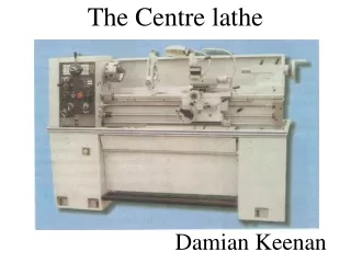
Session 3 • Classification of lathes • Kinematics system of centre lathe • Working principle of lathe machine
Classification of lathes • Lathes are very versatile of wide use and are classified according to several aspects: • (a) According to configuration • • Horizontal • Most common for ergonomic conveniences • Vertical • - Occupies less floor space, only some large lathes are of this type.
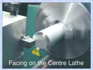
Classification of lathes • (b) According to purpose of use • General purpose • Very versatile where almost all possible types of operations are carried out on wide ranges of size, shape and materials of jobs; example : centre lathes • Single purpose • Only one (occasionally two) type of operation is done on limited ranges of size and material of jobs; example – f acing lathe, roll turning lathe etc. • Special purpose • - Where a definite number and type of operations are done repeatedly over long time on a specific type of blank; example: gear blank machining lathe etc.
Classification of lathes • (C)According to size or capacity • • Small (low duty) • - In such light duty lathes (upto 1.1 kW), only small and medium size jobs of generally soft and easily machinable materials are machined • • Medium (medium duty) • - These lathes of power nearly upto 11 kW are most versatile and commonly used • • Large (heavy duty) • • Mini or micro lathe • - These are tiny table-top lathes used for extremely small size jobs and precision work; example : swiss type automatic lathe
Classification of lathes • (D)According to degree of automation • • Non-automatic • - Almost all the handling operations are done manually; example: centre lathes • • Semi-automatic • - Nearly half of the handling operations, irrespective of the processing operations, are done automatically and rest manually; example : capstan lathe, turret lathe, copying lathe relieving lathe etc. • • Automatic • - Almost all the handling operations (and obviously all the processing operations) are done automatically; example – single spindle automat (automatic lathe), swiss type automatic lathe, etc.
Classification of lathes • (E)According to type of automation • • Fixed automation • - Conventional; example – single spindle automat, swiss type automatic lathe etc. • • Flexible automation • - Modern; example CNC lathe, turning centre etc. • (f) According to configuration of the jobs being handled • • Bar type • - Slender rod like jobs being held in collets • • Chucking type • - Disc type jobs being held in chucks • • Housing type • Odd shape jobs, being held in face plate
Classification of lathes • (g)According to precision • • Ordinary • • Precision (lathes) • - These sophisticated lathes meant for high accuracy and finish and are relatively more expensive. • (h) According to number of spindles • • Single spindle • - Common • • Multispindle (2, 4, 6 or 8 spindles) • - Such uncommon lathes are suitably used for fast and mass production of small size and simple shaped jobs.
Classification of Lathes Bench Lathe
Lathe Components • Bed: • It supports all major components of lathe as it is the base of machine. • These have large mass, rigidly built as single piece casting from gray/ toughened C.I to resist deflection & absorb vibrations generated during cutting process. • Three main parts head, tail stocks , carriage are mounted on bed
2. Head stock: • It is a part which secured permanently at left hand end of bed which supports spindle & equipped with power driving mechanisms (motors, pulleys, V-belts ) for spindle at various rotational speeds. • It have a hollow spindle to which Work holding devices such as chucks, collets are attached.
3. Tail stock/ Loose head stock/ Puppet head: • It is mounted on inner ways at right hand end of bed which can slide along the ways & can be clamped at any position, supports the other end of w/p. • It is equipped with a centre that may be fixed(dead centre) or may be free to rotate with w/p called (live centre) • Drills & reamers can be mounted on tailstock quill (a hollow cylindrical part with tapered hole) to drill axial holes in w/p. Quill can move in & out with hand wheel.
Carriage: • It slides along the guide ways between head stock, tailstock & consist of assembly of saddle, cross slide, tool post, compound rest, apron. • Main function of carriage is to hold cutting tool & move it to give longitudinal & / cross feed to it. • Operator moves carriage manually by hand wheel/ automatically by engaging feed shaft with carriage feed mechanism.
Carriage consists of: • Saddle: • Part of carriage which slides along bed ways & support the cross slide, compound rest, tool post. • Cross slide: • Mounted on top of saddle & always moves in direction normal to axis of main spindle. • It can be either operated by hand by means of cross feed screw or may be given power feed through apron mechanism.
c) Compound rest: • It is mounted on cross slide & carries a graduated circular base called as swivel plate. • Upper part is called compound slide can be moved by means of compound rest feed screw. • Tool post: • Top most part of carriage, used for holding tool/ tool holder in position.
e) Apron: • It is hanging part in front of carriage. • It serves as housing for number of gear trains through which power feeds can be given to the carriage & cross slide.
5. Feed rod & Lead screw: • Feed rod is powered by set of gears from head stock. • It rotates during operation of lathe & provides movement to carriage & cross-slide by means of gears, friction clutch, key way along the length of rod. • Lead screw it transmits power to carriage through a gear & clutch arrangement in carriage apron.
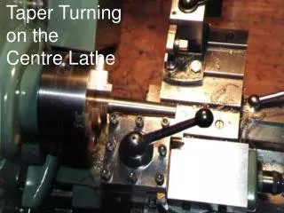
Working Principle of lathe • The lathe is a machine tool which holds the work piece between two rigid and strong supports called centers or in a chuck or face plate which revolves as shown in Fig. • The cutting tool is rigidly held and supported in a tool post which is fed against the revolving work. • The normal cutting operations are performed with the cutting tool fed either parallel or at right angles to the axis of the work. • The cutting tool may also be fed at an angle relative to the axis of work for machining tapers and angles.