Download
1 / 20
200 likes | 230 Views
Team 5 presents detailed analysis of airfoil sections, wing and tail geometry, and mathematical models for optimal aerodynamic performance in AAE 451 project.

E N D
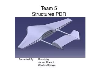
Team 5Aerodynamics PDR Presented By: Christian Naylor Eamonn Needler Charles Reyzer
Outline • Airfoil Sections • Wing/Tail Geometry, Areas • Mathematical Models • Incidence Angles • Control Surfaces • Endurance AAE 451 – Team 5
Airfoil Sections – Wing • Wing • Eppler E212 • Tail • Eppler E169 Horizontal Tail • NACA 0010 Vertical Tail AAE 451 – Team 5
Geometry – Wing • Sizing • Weight : 0.6 lbs • W/S: 0.38 lbs/ft2 • Wing Area: 1.58 ft2 • Geometry Simplification • 2 Trapezoid Sections AAE 451 – Team 5
Geometry – Wing • Defined Sweep Angles (Λ) • Defined taper ratio (λ) of 1st segment • Defined Span Ratio of 2 segments • Adjust to balance • Style • Aspect Ratio • Tip Chord feasibility AAE 451 – Team 5
Geometry – Wing • Find Mean Aerodynamic Chord and Aerodynamic Center: AAE 451 – Team 5
Geometry – Tail • Define Tail Volume Coefficients based on similar aircraft: • Cvt = 0.04 • Cht = 0.50 • Find tail areas • Svt=cvtbS/Lvt = 0.20 sq ft • Sht=chtcS/Lht = 0.47 sq ft AAE 451 – Team 5
Geometry – Wing AAE 451 – Team 5
Mathematical Model AAE 451 – Team 5
Mathematical Model – Lift • Prandtl Lifting Line Theory1 • Elliptical Lift Distribution 1 Anderson, J.D., Fundamentals of Aerodynamics, New York, 2001, pp 351-416 AAE 451 – Team 5
Mathematical Model – Lift Spanwise Γ Distribution Spanwise Downwash Distribution w(y) (m2/ft2s) Γ(y) (m2/s) Span (ft) Span (ft) AAE 451 – Team 5
Mathematical Model – Lift Curve Spanwise Lift Coefficient Distribution Lift Coefficients vs. α CL and Cl CL Span (ft) α (deg) CLmax (Hembold): 0.74 Max Lift (Hembold): 1.10 lbf Max Lift at Cruise α: 0.74 lbf AAE 451 – Team 5
Mathematical Model – Drag • Calculated from Lifting Line Theory1 • e=0.75 Drag Polar CD CL 1 Anderson, J.D., Fundamentals of Aerodynamics, New York, 2001, pp 351-416 AAE 451 – Team 5
Mathematical Model – Moment Pitching Moment vs. α CM and Cm α (deg) 2 Raymer, D.P., Aircraft Design: A Conceptual Approach, Virginia, 1999, pp 315-378,493-494 AAE 451 – Team 5
Mathematical Model – L/D • L/Dmax=11.89 • Cruise at α=3° L/D vs. α L/D α (deg) AAE 451 – Team 5
Incidence Angles Spanwise Induced α αi Span (ft) AAE 451 – Team 5
Control Surfaces • Ailerons • 50% to 90% on span • 15% to 25% of chord • Used junction to 95% chord and 25% of chord • Elevator • 0% - 90% on span • 25% to 50% of chord • Used 75% of span and 50% chord • Rudders • Same typical ranges as elevators • Used 10% to 90% on span and 50% chord AAE 451 – Team 5
Control Surfaces • Sizes • Aileron Area: 0.082 ft2 (each) • Elevator Area: 0.176 ft2 • Rudder Area: 0.039 ft2 (each) AAE 451 – Team 5
Endurance • Battery Wgt. Fraction = 0.064 • Battery Weight = 0.038 lbs. AAE 451 – Team 5
Future Work • Revisit Sizing Code • Revisit Aerodynamic Center/ CG Calculations • Revisit Spanwise Lift Distribution • Look at Trade Studies AAE 451 – Team 5