Download
1 / 103
1.04k likes | 1.17k Views
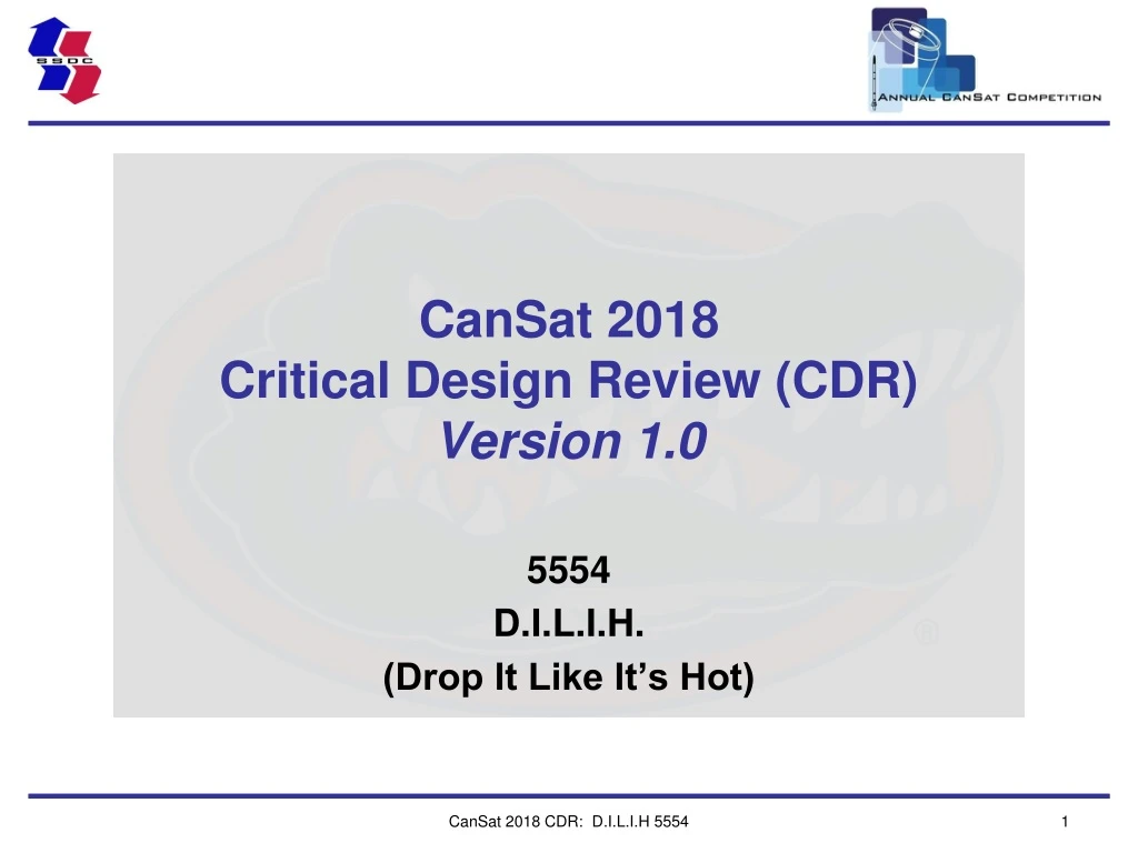
CanSat 201 8 Critical Design Review (CDR) Version 1. 0. 5554 D.I.L.I.H. (Drop It Like It’s Hot). Presentation Outline. Systems Overview - John Kempienski, Samuel Buckner, Jacob Gusewelle, Richard Spoerl

E N D
CanSat 2018Critical Design Review (CDR)Version 1.0 5554 D.I.L.I.H. (Drop It Like It’s Hot) CanSat 2018 CDR: D.I.L.I.H 5554
Presentation Outline • Systems Overview - John Kempienski, Samuel Buckner, Jacob Gusewelle, Richard Spoerl • Sensor Subsystem Design - John Kempienski, Zane Gyorko, Stephen Supinski, Aastha Rajbhandary • Descent Control - John Kempienski, Richard Spoerl, Jacob Gusewelle • Mechanical Subsystem Design - John Kempienski, Samuel Buckner, Jacob Gusewelle, Stephen Supinski • Communication and Data Handling - John Kempienski, Cullen Quagliana, Zane Gyorko • Electrical Power Subsystem - John Kempienski, Zane Gyorko • Flight Software Design - John Kempienski, Aastha Rajbhandary, Cullen Quagliana • Ground Control System - John Kempienski, Zane Gyorko • CanSat Integration and Test - John Kempienski • Mission Operation and Analysis - John Kempienski • Requirements– John Kempienski • Management– John Kempienski Presenter: John Kempienski CanSat 2018 CDR: D.I.L.I.H 5554
Team Organization • Presenter: John Kempienski CanSat 2018 CDR: D.I.L.I.H 5554
Acronyms • A – Analysis • ABHS – Aerobraking Heat Shield • ABS – Acrylonitrile butadiene styrene • Avg – Average • CDH – Communication and Data Handling • CDR – Critical Design Review • CR – Communication and Data Handling Subsystem Requirements • D – Design • DR – Descent Control Requirements • EPS – Electrical Power Subsystem • ER – Sensor Subsystem Requirements • FSW – Flight Software • FTDI – Future Technology Devices International • GCS – Ground Control System • GPS – Global Positioning System • GR – Ground Control System Requirements • GS – Ground Station Presenter: John Kempienski CanSat 2018 CDR: D.I.L.I.H 5554
Acronyms • GUI – Graphical User Interface • H – High • I – Inspection • IDE – Integrated Development Environment • L – Low • LED – Light Emitting Diode • M – Medium • MR – Mechanical Subsystem Requirements • OBC – Onboard Computer • PCB – Printed Circuit Board • PDR – Preliminary Design Review • PR – Electrical Power Subsystem Requirements • RTC – Real-Time Clock • SR – System Requirements • T – Test • TR – Integration and Test Requirements • VSWR – Voltage Standing Wave Ratio Presenter: John Kempienski CanSat 2018 CDR: D.I.L.I.H 5554
Systems Overview John Kempienski Samuel Buckner Jacob Gusewelle Richard Spoerl CanSat 2018 CDR: D.I.L.I.H 5554
Mission Summary • Mission Objectives • Simulate a vehicle which samples planetary atmospheric data, equipped with a detachable aerobraking heatshield, carrying sensitive payload (egg) • The probe shall refer to the structure containing the CanSat electronics • The CanSat shall consist of the aerobraking heat shield (ABHS) and the probe Fig. 1.1 CanSat Model Presenter: John Kempienski CanSat 2018 CDR: D.I.L.I.H 5554
Summary of Changes Since PDR • Summary of changes since PDR • Electronics with sensors will require at least 2 PCBs • Details of the changes are discussed in subsequent sections Presenter: John Kempienski CanSat 2018 CDR: D.I.L.I.H 5554
System Requirement Summary Presenter: John Kempienski CanSat 2018 CDR: D.I.L.I.H 5554
System Concept of Operations • Pre-launch activities • CanSat system inspection, ground station setup, official check-in, load rocket • Launch and descent operations • Establish communication between CanSat and Ground Station • Begin data acquisition • Ejection from rocket at apogee (600m) • CanSat relays sensor data, deploys ABHS, begins stabilized descent • Release ABHS, deploy parachute (300m) • CanSat lands, telemetry saved, last known GPS location recorded • Post launch recovery and data reduction • GPS location used to locate CanSat • Data is analyzed • Team member roles and responsibilities on launch day • Discussed on the Overview of Mission Sequence of Events slide Presenter: Richard Spoerl CanSat 2018 CDR: D.I.L.I.H 5554
System Concept of Operations 3 2 4 1 Fig. 1.2 CONOPS Flight Diagram • Presenter: Richard Spoerl CanSat 2018 CDR: D.I.L.I.H 5554
Payload Physical Layout ABHS Configurations and Dimensions ABHS: Deployed ABHS: Stowed 110 mm Spring loaded ribs 78 mm Hinges with springs 225 mm Nosecone Fig. 1.4 Deployed configuration Fig. 1.3 Stowed configuration Presenter: Jacob Gusewelle CanSat 2018 CDR: D.I.L.I.H 5554
Payload Physical Layout (100 mm) • Parachute will be attached to the top of the probe • Containment mechanisms: • Parachute • Fishing line melted with nichrome wire • ABHS nose cone • Fishing line and nichrome wire Probe Dimensions and Placement of Components Space for parachute or electronics (50 mm) Foam egg housing (75 mm) (225 mm) Electronics (100 mm) Fig. 1.5 Probe dimensions • Presenter: Jacob Gusewelle CanSat 2018 CDR: D.I.L.I.H 5554
Launch Vehicle Compatibility • All clearances displayed relative to rocket envelope • 1 cm radial clearance • Allows for easy deployment • 1mm top/bottom clearance • Outside parts will be 3D printed with tolerance <0.2mm • Nose cone shall have flat tip • Avoids sharp protrusion • Fillets added to all potential protrusions 1 cm 1 mm Fig. 1.6 Launch vehicle clearances Presenter: Samuel Buckner CanSat 2018 CDR: D.I.L.I.H 5554
Sensor Subsystem Design John Kempienski Zane Gyorko Stephen Supinski Aastha Rajbhandary CanSat 2018 CDR: D.I.L.I.H 5554
Sensor Subsystem Overview • All sensors are chosen to be compatible with the chosen OBC • Sensor subsystem shall encompass all necessary sensors, consisting of: • Air pressure (BME280), air temperature (BME280), GPS location (LLC746), and tilt (MMA8452Q) for environmental data • Voltage sensor (resistor ladder) to monitor EPS status • Light sensor (GA1A1S202) to detect transition states • Flight ready system will be PCB based and mounted securely within the probe Fig. 2.1 Digital PCB prototype of selected sensors Presenter: John Kempienski CanSat 2018 CDR: D.I.L.I.H 5554
Sensor Changes Since PDR • Electronics with sensors will require at least 2 PCBs • Layout of structural and electronic components limits space available • Single board would be too small for all necessary components • PCBs will be interconnected and part of a singular circuit controlled by one OBC CanSat 2018 CDR: D.I.L.I.H 5554
Sensor Subsystem Requirements Presenter: John Kempienski CanSat 2018 CDR: D.I.L.I.H 5554
GPS Sensor Summary • Selected GPS: Adafruit LLC 746 • Data accuracy and format • 2.5 m positional accuracy • 145 dBm acquisition sensitivity • 10Hz update rate • Data processing • GPS data is read as NMEA sentences. These sentences will be parsed and appended to telemetry packet. • Included software libraries provide functions to easily retrieve required data (position, time, etc.) • Update rate will be at least 1Hz and stored locally, most recent data will be sent with each packet transmission Fig. 2.3 Adafruit LLC 746 Presenter: Stephen Supinski CanSat 2018 CDR: D.I.L.I.H 5554
Probe Air Pressure and Temperature Sensor Summary • Selected Pressure Sensor: BMP280 • Provides both pressure and temperature data • 0.16 Pa resolution for pressure data • 0.01 C resolution for temperature data • Data processing • Pressure output will be used to determine current altitude • Included software library provides function to calculate this • Where: • is the measured pressure • is the pressure at sea level (101325 Pa) Fig. 2.2 Adafruit BME280 • Presenter: Zane Gyorko CanSat 2018 CDR: D.I.L.I.H 5554
Probe Power Voltage Sensor Summary • Selected Voltage Sensor: OBC Analog Input (Voltage Divider) • Data accuracy and format • Manufacturer specified accuracy of 7.8% • Expected performance margins are much smaller and will be tested to confirm 3% or less error upon completion of probe PCB • Input values range from 0-3.3V • Voltage divider in line to meet restraints • Data processing • Voltage value measured at analog input will be processed using the ratio of the voltage divider • Accurate probe EPS voltage measurement will be returned for transmission with telemetry packet Fig. 2.4 Voltage divider example Presenter: Zane Gyorko CanSat 2018 CDR: D.I.L.I.H 5554
Tilt Sensor Summary • Selected Tilt Sensor: MMA8452Q • Data accuracy and format • Sensitivity: 256 counts/g • Accuracy: 20 mg (zero-g level offset) • Data processing • Digital output will provide X, Y, and Z acceleration values • Returned data will be processed through included library functions to reflect real-world probe orientation Fig. 2.5 MMA8452Q accelerometer Presenter: Zane Gyorko CanSat 2018 CDR: D.I.L.I.H 5554
Light Sensor Summary • Selected Light Sensor: GA1AS202 • Data accuracy and format • 10-bit accuracy • Uses OBC ADC interface • Data processing • Analog voltage reference is read from sensor output • Light value limits will determine a state change • Will detect deployment from rocket Fig. 2.6 GA1AS202 Light Sensor Presenter: Zane Gyorko CanSat 2018 CDR: D.I.L.I.H 5554
Descent Control Design John Kempienski Richard Spoerl Jacob Gusewelle CanSat 2018 CDR: D.I.L.I.H 5554
Descent Control Overview • The descent control system consists of the ABHS and a parachute • Both will be attached to the probe. • Inside rocket: • Nylon fishing line compresses the ABHS and parachute • Nylon fishing line connects the ABHS to the probe. • Deployment of CanSat: • Occurs following apogee around 600 meters • Nichrome wire melts nylon deploying ABHS, stabilizing descent • At 300 meters: • Nichrome wire melts remaining nylon • This will release the ABHS from the probe and deploy the parachute • The probe then descents to the ground. CanSat Descent Deployment from rocket, open ABHS 600 m ABHS and Parachute Release Altitude 300 m Probe + Parachute ABHS Time Fig. 3.2 Descent sequence Fig. 3.1 Descent graph Presenter: John Kempienski CanSat 2018 CDR: D.I.L.I.H 5554
Descent Control Changes Since PDR • No major changes since PDR • Prototype testing • FEA simulations confirm arm rigidity under wind drag • Drop test confirm desired stability and descent speed during deployed configuration • Table top testing confirm nichrome/nylon release functionality CanSat 2018 CDR: D.I.L.I.H 5554
Descent Control Requirements Presenter: John Kempienski CanSat 2018 CDR: D.I.L.I.H 5554
Payload Descent Control Hardware Summary • Flaps are secured using nylon fishing line • Deployment occurs upon melting the nylon via nichrome wire Stowed Configuration Deployed Configuration *Heat shield not pictured Fig. 3.3 Stowed ABHS Fig. 3.4 Deployed ABHS • Presenter: Richard Spoerl CanSat 2018 CDR: D.I.L.I.H 5554
Payload Descent Control Hardware Summary Deployment Method: • Each individual flap has a spring connected to the base of the ABHS • The springs force the flaps open and the drag slows the descent of the probe Fig. 3.5 ABHS arm configuration • Presenter: Richard Spoerl CanSat 2018 CDR: D.I.L.I.H 5554
Payload Descent Control Hardware Summary Probe parachute: Apogee 30” nylon • Key Considerations: • Spill hole cut into center provides desired descent rate of 5m/s • Color will be a fluorescent orange Fig. 3.6 Apogee 30” nylon • Presenter: Richard Spoerl CanSat 2018 CDR: D.I.L.I.H 5554
Descent StabilityControl Design • Design: Spin andStatic Margin • The design is passively kept nadir point by: • Spinning about the long vertical axis due to the groves on the nose cone. • Static margin, the distance between the center of pressure and center of mass Static Margin Center of Drag Center of Mass Fig. 3.7 Design model • Presenter: Jacob Gusewelle CanSat 2018 CDR: D.I.L.I.H 5554
Descent Rate Estimates • Descent rates to determine • Terminal Velocity of Probe + ABHS • Terminal Velocity ABHS • Velocity of Probe after release of ABHS • Assumptions • Air density is negligible and computed at sea-level; 1.225 kg/m3 • ABHS has a coefficient of drag of 0.5 • The parachute deploys after the release of the ABHS • ABHS always falls in the correct orientation • Equations used • (from Newtons Second Law) : acceleration : Coefficient of Drag Air density : Velocity : Area : mass : gravity Presenter: John Kempienski CanSat 2018 CDR: D.I.L.I.H 5554
Descent Rate Estimates • Derived equations: • Terminal Velocity (occurs when a = 0, or W = D) • Velocity = (derivative of a; x=(-drop height)) • Drop Test – Experimental Confirmation • ABHS with added weight to simulate probe dropped from a height of 1.11m • Expected velocity at drop height: 9.12 m/s • Observed velocity at drop height: 9.17 m/s • Error: 0.6% • Probe + ABHS is projected to be within acceptable descent rage of 10-30 m/s within 2 seconds after deployment Presenter: John Kempienski CanSat 2018 CDR: D.I.L.I.H 5554
Descent Rate Estimates • Estimated results: • Terminal Velocity of Probe + ABHS : 18 m/s • Expected to fall 132m before reaching terminal velocity • Terminal Velocity does not exceed desired descent rate range • Terminal Velocity ABHS : 13 m/s • Velocity of Probe after release of ABHS : 5 m/s • Controlled by parachute Presenter: John Kempienski CanSat 2018 CDR: D.I.L.I.H 5554
Mechanical Subsystem Design John Kempienski Samuel Buckner Jacob Gusewelle Stephen Supinski CanSat 2018 CDR: D.I.L.I.H 5554
Mechanical Subsystem Overview • Aerobraking Heat Shield - ABHS • Heat Shield: Thermal Blanket • Frame (Ribs and nose cone): ABS plastic, Steel pins, Steel springs • Stowed configuration: Frame is folded against probe using nylon wire • Deployed configuration: At 600m nichrome burns nylon which allows frame to expand • Probe • Body: ABS plastic, steel screws, steel PCB standoffs, cotton, plexiglass, steel swivel • Parachute: Nylon • Stowed configuration: Parachute and ABHS attached with nylon wire • Deployed configuration: At 300m second nichrome burn releases ABHS and parachute Presenter: John Kempienski CanSat 2018 CDR: D.I.L.I.H 5554
Mechanical Subsystem Changes Since PDR • No major changes since PDR CanSat 2018 CDR: D.I.L.I.H 5554
Mechanical Sub-System Requirements Presenter: John Kempienski CanSat 2018 CDR: D.I.L.I.H 5554
Mechanical Sub-System Requirements Presenter: John Kempienski CanSat 2018 CDR: D.I.L.I.H 5554
Probe Mechanical Layout of Components • Probe will be manufactured using ABS plastic • Egg will be protected with cylindrical antistatic foam • Located between four rods in the middle of the probe • The probe shall open at the center • Twists into/out of grooves for easy access to payloads • Electronics bay • Located under the egg bay and on top of the detachable lid • The lid serves as the mounting point (using screws and standoffs) for the electronics • Heat Shield & Parachute interface • Nylon wire attached to fixed nichrome wires hold the two components in place Parachute Bay (50 mm) Egg Protection Bay (75 mm) Probe Twist-Opening Electronics Bay (100 mm) Detachable lid Fig. 4.1 Separate structure model Nichrome-Nylon Attachment Points • Presenter: Samuel Buckner CanSat 2018 CDR: D.I.L.I.H 5554
Egg Protection Mechanical Layout of Components Egg protection bay • The two interlocking halves meet in the middle of the protection bay • Bubble wrap is placed in both halves • The probe is assembled with the egg in one half while the other end is placed over and locked. Probe Twist-Opening Fig. 4.2 Interlocking design model Presenter: John Kempienski CanSat 2018 CDR: D.I.L.I.H 5554
Heat shield Release Mechanism • Pre-deployment: • Arms are connected to nose cone using hinges • Arms are secured in the stowed configuration • Nylon fishing line is fed through holes in top of arms • Nylon line is connected to a piece of nichrome wire • ABHS nose cone is secured to bottom of probe • Nylon fishing line secures probe to ABHS • Pre-release: • ABHS is protecting probe and stabilizing descent of CanSat system • Deployed configuration • ABHS remains connected to probe via nylon line • Release action: • Nichrome wire activates at defined altitude • Melts nylon line connecting ABHS to probe • Probe releases from ABHS at their only connection point Holes for nylon ABHS – Probe attachment point Fig. 4.3 Nylon line feed points • Presenter: Samuel Buckner CanSat 2018 CDR: D.I.L.I.H 5554
Probe Parachute Release Mechanism • Parachute will be internally attached to probe • Fastened to support bars • Parachute will be attached to a swivel to increase stability • Parachute will be exposed on top of probe • Held in place by overlapping nylon line • Nylon line will run over top of the parachute in an ‘X’ pattern • Parachute will be folded such that • When nylon is melted, parachute will collect air and deploy autonomously Holes for fishing line to secure parachute Support bars for fastening the parachute Nylon line configuration Fig. 4.4 Parachute release mechanisms • Presenter: Richard Spoerl CanSat 2018 CDR: D.I.L.I.H 5554
Structure Survivability Electronic component mounting methods • The PCB will be mounted to the probe using standoff. • The light sensor and nichrome wire will be hot glued to their respective positions on the probe. Electronic component enclosures • The electronics will be entirely enclosed inside of the probe. • The enclosure will have openings to see LEDs, access nichrome. • The enclosure will be easily removable to access the electronics. Acceleration and Shock force testing • CanSat will be subjected to shock force testing. • All components are expected to survive 30 Gs of shock based on load ratings. Securing electrical connections • Secured with a combination of crimp connectorsand electrical grade RTV. • The crimp connectors act by deforming the wire and pin together, making it nearly impossible to sever the connection. • The RTV will expand inside the crimp housing, improving connection strength. • RTV will also be used to mount sensors and PCB board together, as it is a durable, general purpose, and electrically safe adhesive. Descent control attachments • 40lb nylon fishing line will be used to attach all descent controls to the probe • Line weight exceeds the maximum loads calculated based on acceleration and shock requirements. • Presenter: Stephen Supinski CanSat 2018 CDR: D.I.L.I.H 5554
Mass Budget • Total Mass with uncertainty is under 500 grams • Dummy weights (lead) will be used increase the weight of the ABHS nose cone to 500g Presenter: John Kempienski CanSat 2018 CDR: D.I.L.I.H 5554
Communication and Data Handling (CDH) Subsystem Design John Kempienski Cullen Quagliana Zane Gyorko CanSat 2018 CDR: D.I.L.I.H 5554
CDH Overview • Onboard Computer • Teensy 3.2 • The CanSat OBC and master of CDH data system • Electronics • Gather telemetric data • I2C interface to communicate with microcontroller • Communications • Xbee radio with GSM-02-SM antenna • Transmit data to ground station Fig. 5.2 XBee Radio Fig. 5.1 Teensy 3.2 Presenter: John Kempienski CanSat 2018 CDR: D.I.L.I.H 5554
CDH Changes Since PDR • Removed use of standalone RTC module • Selected OBC has available built in RTC • Requires use of independent battery to maintain accuracy during power loss • Despite battery requirement, built in RTC will reduce mass, area, and complexity of probe electronics • Zero loss in data accuracy Presenter: Name goes here CanSat 2018 CDR: D.I.L.I.H 5554
CDH Requirements Presenter: John Kempienski CanSat 2018 CDR: D.I.L.I.H 5554
Probe Processor & Memory Selection • Selected Processor: Teensy 3.2 • Processor Speed: 72MHz • Memory: 256 MB • Data Interfaces • Serial, I2C, ADC • All interfaces required to use selected sensors and other electronics are present • Arduino IDE provides easy, familiar, and widely supported environment for software development Fig. 5.3 Teensy 3.2 pinout diagram CanSat 2018 CDR: D.I.L.I.H 5554 Presenter: Cullen Quagliana