Download
1 / 29
290 likes | 317 Views
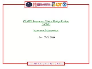
BUNKER SYSTEM DOCUMENTATION Critical Design Review (CDR) 5 December 2017. Mark Ridgley Technical Documentation Coordinator Bunker Project europeanspallationsource.se. Bunker System Life-cycle ConOps ESS-0123251. CONSTRUCTION. OPERATIONS. DECOMMISSIONING. DESIGN. 2013.

E N D
BUNKER SYSTEMDOCUMENTATIONCritical Design Review (CDR)5 December 2017 Mark Ridgley Technical Documentation Coordinator Bunker Project europeanspallationsource.se
Bunker System Life-cycleConOps ESS-0123251 CONSTRUCTION OPERATIONS DECOMMISSIONING DESIGN 2013 2016 2017 2019 2023 2065 TBD PRELIMINARY ENGINEERING DESIGN FINALENGINEERING DESIGN CONSTRUCTION & INSTALLATION BEAM TEST & COMMISSIONING GENERAL OPERATIONS PLUS MAINTENANCE, UPGRADES & DEVELOPMENT DECOMMISSIONING& DISPOSAL FIRST BEAM ON TARGET HANDOVER PDR CDR SAR ORR KICK-OFF
Bunker Project DocumentationDelivered for CDR • Final design definition in the form of: • Neutronics simulations and analysis • 3D engineering models • Engineering simulations and analysis • Engineering documentation for manufacturing procurement • Systems Documentation • Concept of Operations (ConOps) • System Requirements Specification (SRS) • System Architecture Descriptions (SAD) • Systems Design Description (SDD) • System Integration Plan (SIP) • System Verification Plan (SVeP) • System Validation Plan (SVaP) • System Operation and Maintenance Manual (SOMM) • System Interface Description (SID)
Bunker System Documentationw.r.t. PSAR and SSM • Preliminary Safety Assessment (PSAR) as presented to Swedish Radiation Safety Authority (SSM) • Section 3.2. Radiation Safety Analyses & Methodologies • Illustration of ESS design process as defined in the system engineering management plan
ESS Facility Breakdown StructureCHESS =ESS.NSS.F01.F01 Bunker System Shielding & Safety System
Bunker System DocumentationESS-0123251 - Concept of Operations (ConOps) • Primary purpose - provide a shared cavity shielding bunker at the target monolith to: • Host Instrument Systems front-end elements. • Attenuate the radiation emanating from the target monolith and generated in the first sections of the beam-lines (neutron and gamma rays) to safe levels external to the bunker. Bunker System ConOps Scope:
Bunker System DocumentationESS-0060210 - System Requirements Specification (SRS) • SRS specifies and describes the system requirements for the Bunker System (BS.SyR). • Derived from: • high-level requirements allocated by the parent system - Shielding & Safety System • ConOps for the Bunker System • feedback from the evolving design development of the system • BS.SyR are defined according to the different categories and each is uniquely identified: • Functional Requirements • Constraint Requirements • Seismic Safety Requirements • Radiation Safety Requirements • Interface Requirements • BS.SyR are applied to the requirements driven development of the system design.
Bunker System DocumentationESS-0123443 - System Architecture Description (SAD) • SAD describes the system architecture and allocation of BS.SyR to subsystems. • BS.SyR are allocated to at least one subsystem. Bunker System Breakdown Structure (simplistic)
Bunker Subsystem DocumentationESS-0123282 - ConOps for the Bunker Structural Support System • System purpose of the Bunker Structural Support System is to: • provide the load paths through to the bunker base of the Monolith Civil Structure (MCS) in D-Building D02 (Target Building) and the bunker base in D01 (Experimental Hall 1) and D03 (Experimental Hall 2) to resist dead load, live loads and accidental loads. • provide structural support for the bunker roofs. • provide interfaces for the routing of required utilities within the bunker. • provide the structure that ensures Bunker System requirements at H4 seismic event are fulfilled. • allow for the allocation of reserved volume for each Instrument System (IS) along its designated beam-port central axis from the target to the bunker walls for its front-end system elements installed within the bunker.
Bunker Subsystem DocumentationESS-0123283 - ConOps for the Bunker Wall System • System purpose of the Bunker Wall System is to: • provide attenuation of radiation emanating outwards from within the bunker down to safe levels external to the bunker. • ensure attenuation of radiation emanating from within the bunker through where the base of the bunker walls interface with the bunker base respectively in the Monolith Civil Structure (MCS) of D-Building D02 (Target Building), in D-Building D01 (Experimental Hall 1) and D-Building D03 (Experimental Hall 2) down to safe levels external to the bunker. • modular in form to provide safe feed-through of Instrument Systems (IS) elements (e.g. instrument guides) from within the bunker into D01 and D03 respectively. • modular in form to allow modification to suit installation or removal of IS elements (e.g. instrument guide). • modular in form to provide safe feed-through routing of utilities into the bunker from D01 and D03 for IS elements within the bunker. • impede access to the bunker. • modular in form to provide restricted secondary access for the passage of large IS elements for installation or removal when access passage through the bunker roof is not sufficient.
Bunker Subsystem DocumentationESS-0123286 - ConOps for the Bunker Roof System • System purpose of the Bunker Roof System is to: • provide attenuation of radiation emanating upwards from within the bunker down to safe levels external to the bunker. • modular in form to provide restricted personnel access to the bunker. • modular in form to provide primary access for the passage of Instrument Systems elements, Target Systems elements and associated equipment for installation or removal.
Bunker Subsystem DocumentationESS-0123281 - ConOps for the Bunker Access Safety System • System purpose of the Bunker Access Safety System is to: • provide safe restricted authorised personnel access to the bunker roofs. • provide safe restricted authorised access into the bunker.
Bunker System DocumentationSystem and Subsystems Refer to: BunkerSystem-doc.tif
Bunker System DocumentationESS-0087572 - System Interface Description (SID) • SID captures and describes project specific interface agreements with neighbouring systems; Site Infrastructure, Target Systems and Instrument Systems: • ESS-0062997, Bunker shielding roof seismic load on MCS • ESS-0085422, Boundary interfaces definition; Bunker – CF • ESS-0068165, Bunker layout – Interfaces – static load • ESS-0084435, Bunker pillar loads calculation • ESS-0086197, Bunker to the insert exchange tool interface • ESS-0051975, Bunker base support pillars • ESS-0062215, Feed-thru block assembly • ESS-0062127, Short instrument wall feed-thru outline • ESS-0062152, Long instrument wall feed-thru • ESS-0086538, Utilities feed-through layout • ESS-0086925, Bunker to Target interfaces • ESS-0049906, ICD-R NBEX-NSS • The agreed to interface solutions at preliminary design stage and used as input into the final design engineering.
Bunker System DocumentationESS-0123264 - System Design Description (SDD) • SDD provides the documented description of the design of the Bunker System that is to be built. • SDD is comprised of the SDDs of its subsystems. • SDD captures for subsystems and complete system: • Design engineering • 3d models. • Simulations & analysis. • Engineering drawings for manufacture procurement. • Neutronics • Simulations & analysis.
Bunker System DocumentationESS-0123264 - System Design Description (SDD) Bunker System Product Breakdown
Bunker System DocumentationESS-0123264 - System Design Description (SDD) Bunker Structural Support System Product Breakdown ESS-0123449 SDD
Bunker System DocumentationESS-0123264 - System Design Description (SDD) Bunker Wall System Product Breakdown ESS-0123450 SDD
Bunker System DocumentationESS-0123264 - System Design Description (SDD) Bunker Roof System Product Breakdown ESS-0123452 SDD
Bunker System DocumentationESS-0123264 - System Design Description (SDD) Bunker Access Safety System Product Breakdown ESS-0123448 SDD
Bunker System DocumentationESS-0123956 - System Integration Plan (SIP) • SIP provides the documented description of the plan for integration of the Bunker System into the ESS facility. • SIP is comprised of the SIPs of its subsystems. • Subsystem SIPs developed from respective subsystem SDD. • Captures the design engineers’ plan that is the input provided to the project installation plan. • System Verification and Validation are generally carried out as the system integration progresses and close out at its completion.
Bunker System DocumentationESS-0123956 - System Integration Plan (SIP) Bunker System Integration
Bunker System DocumentationSystem Integration, Verification and Validation Refer to: BunkerSystem-integration.tif
Bunker System DocumentationESS-0123957 - System Verification Plan (SVeP) • TBA • TBA
Bunker System DocumentationESS-0123947 - System Validation Plan (SVaP) • TBA
Bunker System DocumentationESS-0124440 - System Operations & Maintenance Manual (SOMM) • TBA