Download

1 / 18
190 likes | 253 Views
Learn about the control architecture requirements for wafersteppers, including modules, reliability, DSP-based control, and system operation flexibility for optimal performance in semiconductor manufacturing. Discover the latest advancements in waferstepper technology and how it impacts the semiconductor industry.

E N D
Control Architecture of a waferstepper Gerrit Muller 11-3-1999 Eindhoven Themadag embedded systemen, de keuze tussen software en hardware implementatie
The Market 1997 2002 semiconductor sales by end-user market GDP 33.4 T$ 39.4 T$ 3% 3% non PC computing consumer electronics communications other applications electronic sales 902.4G$ 1284.2G$ PC’s 32% 16% 17% 18% 17% 17% 26% semiconductor sales other semiconductors IC’s memory 151.7G$ 330.6G$ 15% 13% Equipment sales 22.3G$ 42.8G$ equipment 16% 17% steppers Steppers 3.6G$ 7.3G$ ASML sales 1997: 1.8 Gfl net income: 0.3 Gfl source: Dataquest, ING Barings research www.asml.com
Market fluctuations The semiconductor equipment market shows large fluctuations. 1995 1996 1997 1998 units 177 205 211 162 net sales Mfl 918 1331 1803 1717 net profit Mfl 131 218 329 137 Logistic and manufacturing flexibility is a must.
What is a waferstepper? Lightsource Mask (Reticle) Lens Die Wafer
Step & Scan technology reticle Scanning fieldsize Slit Stepping fieldsize Lens Lens wafer 250 mm/s
Main specifications Productivity Imaging Overlay AA (single machine) 40 nm BC (matched) 60 nm 96 Wafers per hour linewidth: 180 nm (1999) critical dimension control For comparison: Wafer diameter 200 mm Die size ca.: 20*20 mm2
Moore’s law (or challenge?) SIA 97 98 99 00 01 02 03 04 05 06 1994 roadmap 250 180 130 1997 roadmap 250 180 150 130 1998 revision 250 180 150 125 1999 proposal 250 180 130 90 leading edge customers 250 180 130 100 linewidth in nm.
Product roadmap ATHENA/TIS 2 kHz laser Quadrupole T1100 193 nm scanner Atlas 300 mm body S400 I-line scanner T400 I-line scanner S700 DUV scanner T700 DUV scanner /900 193 nm scanner 5500 scanner body /400 i-line scanner /500 DUV scanner /700 DUV scanner /300C DUV stepper /300D 5500 stepper body /250C i-line stepper
Modular subsystems illuminator light source reticle handling reticle stage measurement lens UI console contamination and temperature control electronics cabinets wafer handling wafer stage base frame
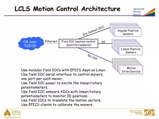
Control architecture requirements • The system can be operated from the operator console or remote • Machine performance is determined by the hardware potential, the control architecture is never a limiting factor • Modules must be independent from manufacturing and logistics point of view, they provide local: • calibration • qualification • safety • diagnostics • Reliable and Robust • Support for localized small improvements (“patches”) • Life cycle support for 10 years
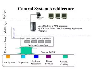
DSP based control DSP based control DSP based control Generic block diagram console remote Sun workstation UNIX Internal network (ethernet) VME VxWorks VME VxWorks VME VxWorks VME VxWorks VME VxWorks VME High speed serial link Position Data bus
Sun Workstation • User interface • Interface to Rest Of World • Persistent storage of recipes, machine constants, monitoring and logging data • Translation of recipes in subsystem activities • High level control (batch control, image quality control) • System set up, qualification and diagnostics software • Downloading of VME/VxWorks subsystems • Never in performance or time critical path (currently not 100% realized, high level control • is sometimes limiting)
Interface management • Major release change if interface(s) change • Patches are possible if no interface is changed • New products on the basis of a major release, consolidation in the next major release
VME/VxWorks time critical controls • Older systems 68k based, newer systems PowerPC based • Process communication via abstraction layer • Communication about subsystem capabilities by “negotiation” • Subsystem synchronization on the basis of a “slow” 4 kHz master clock • Low overheads because of Real time executive (VxWorks)
DSP, number crunching • DSP boards named after first function: Motion controller • Re-use for all number crunching intensive applications • I/O via proprietary Position Data bus and/or High Speed Serial Link • Next generation systems will use PowerPC as signal processor
The analog part The power of the digital control system is entirely determined by the quality of its input. Every measurement system must be designed to obtain a clear (robust, low noise, well defined) signal.
Alignment Scan & Expose control WS control LS control WS actuators x, y, Rz WS actuators z, Rx, Ry Interfe- rometer x, y, Rz Level sensor Align sensor
Summary ASML development strategy • Concurrent engineering • short development cycle time • Networking • market • technology base • flexibility • System engineering • modularity • short integration • Family concept • upgradeability • follow SIA roadmap • reuse, risk reduction over generations