Chapter-6 (D.C. Circuits)
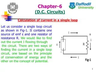
Chapter-6 (D.C. Circuits). Calculation of current in a single loop. Let us consider a single loop circuit as shown in Fig-1. It contains one source of emf ε and one resistor of resistance R. We would like to find out the current I flowing through

Chapter-6 (D.C. Circuits)
E N D
Presentation Transcript
Chapter-6 (D.C. Circuits) Calculation of current in a single loop Let us consider a single loop circuit as shown in Fig-1. It contains one source of emf ε and one resistor of resistance R. We would like to find out the current I flowing through the circuit. There are two ways of finding the current in a single loop circuit, one based on the principle of conservation of energy and the other on the concept of potential.
Chapter-6 (D.C. Circuits) Current from the principle of conservation of energy: If the current in the circuit is I, then in a time dt an amount of energy given by i2Rt appears in the resistor as internal energy. During this same time a charge dq (= idt) moves through the seat of emf. The work done by the seat of emf to move this charge is given by dW = εdq = εidt. From the principle of conservation of energy, the work done by the seat must equal the internal energy deposited in the resistor, i.e., εidt = i2Rt ⇒ i = ε/R.
Chapter-6 (D.C. Circuits) Current from the concept of potential: Referring from Fig-1, let us consider a starting point, say a, whose potential is Va, and traverse the circuit clockwise. In going through the resistor there is a change of potential of –iR. The minus sign indicates that the top of the resistor is at a higher potential than the bottom, (which must be true, because positive charge carriers move of their own accord from high to low potential).
Chapter-6 (D.C. Circuits) Current from the concept of potential: As the battery is traversed from bottom to top, there will be an increase of potential equal to +ε (because the battery has to do positive work on the charge carriers in moving them from a point of lower potential to one of higher potential). When the changes in potential are added algebraically to the initial potential Va, the sum must yield the final value which must be identical to Va. That is, Va –iR +ε = Va ⇒ –iR +ε = 0 ⇒ i = ε/R.
Chapter-6 (D.C. Circuits) Kirchhoff’s laws: Current and resistance in a simple circuit can be determined by using Ohm’s law. But if the circuit is complex then Ohm’s law is not sufficient. For this reasons, Kirchhoff’s two laws are used to calculate current and resistance in a complex circuit. Of course, these laws can also be used in simple circuits. First law or Law of junction: The sum of the currents arriving at any junction must be equal to the sum of the currents leaving that junction. Or, The algebraic sum of the currents meeting at a junction is zero.
Chapter-6 (D.C. Circuits) Explanation: A multi-loop circuit is shown in Fig-2. There are two junctions in this circuit, at b and d (A junction in a multi-loop circuit is a point in the circuit at which three or more wire segments meet. Points a and c are not junctions, because only two wire segments meet at those point). There are three branches in this circuit (A branch is any circuit path that starts on one junction and proceeds along the circuit to next junction), that is there are three paths that connects junctions b and d; left branch bad, the right branch bcd and the center branch bd.
Chapter-6 (D.C. Circuits) The three currents in the three branches are labeled i1 (branch bad), i2 (branch bcd) and i3 (branch bd). The directions of currents have been chosen arbitrarily. Flowing of current means carrying of charge; at junction d, the total rate at which charge enters the junction is given by i1 + i2, and the rate at which charge leaves is given by i2.
Chapter-6 (D.C. Circuits) In the steady state, charge does not collect at or drain away from any point in the circuit. Thus, the rate at which charge enters a junction must be equal to the rate at which it leaves the junction. We therefore, have i1 + i3 = i2 …………… (1). Or, i1 + i3 - i2= 0 Eqn. (1) suggests a general principle for the solution of multi-loop circuits. Thus, we can conclude, the sum of the currents arriving at any junction must be equal to the sum of the currents leaving that junction. Or, the algebraic sum of the currents meeting at a junction is zero.
Chapter-6 (D.C. Circuits) Now, there are three unknowns in the circuit of Fig-2, namely i1, i2 and i3. Applying Kirchhoff’s first law we get only one equation. To solve for the three unknowns, we need two more independent equations. This can be obtained by applying Kirchhoff’s second law, also known as loop rule, which says “the algebraic sum of the changes in potential encountered in a complete traversal of any closed circuit is zero”. Or, “the algebraic sum of the products of currents and resistances in each of the conductors in any closed path (or mesh) in a network plus the algebraic sum of the emfs in that path is zero”. That is .
Chapter-6 (D.C. Circuits) In order to find the potential differences, the following rules will be observed: If a resistance is traversed in the direction of the current, then the change in potential is –iR; in the opposite direction it is +iR. 2. If a seat of emf is traversed in the direction of the emf (i.e., from the negative terminal to the positive rerminal), then the change in potential is +ε; in the opposite direction it is –ε.
Chapter-6 (D.C. Circuits) Now, if we traverse the left loop (abd) if Fig-2 in a counter clockwise direction starting and ending at point b, the loop rule gives ε1 – i1R1 + i3R3 = 0 ……. (2). It is immaterial whether the loop is traversed in a clockwise or counter clockwise direction. The resulting equation will be same. Traversing the right loop (bcd), again in a counter clockwise direction gives, – i3R3 – i2R2 – ε2 = 0 …………. (3).
Chapter-6 (D.C. Circuits)
Chapter-6 (D.C. Circuits) Applications of Kirchhoff’s law In Wheatstone bridge In meter bridge In post office bbox In potentiometer
Chapter-6 (D.C. Circuits) Prob-1: Calculate the currents flowing through the various branches of the circuit shown below.
Chapter-6 (D.C. Circuits)
Chapter-6 (D.C. Circuits)
Chapter-6 (D.C. Circuits) RC circuit: In resistive circuit current will not change with time, but if we introduce a capacitor in a resistive circuit, it forms a RC circuit in which current will vary with time. Let the capacitor C in Fig-3 be charged by throwing the switch S to position a. As soon as the circuit is closed, charge would flow out from the positive terminal of the source of emf and be gradually accumulated in the capacitor C. In a certain time dt an amount of charge dq (= idt) moves through any cross-section of the circuit. The work done by the seat of emf to move this charge is εdq, where ε is the emf of the battery.
Chapter-6 (D.C. Circuits)
Chapter-6 (D.C. Circuits)
Chapter-6 (D.C. Circuits)
Chapter-6 (D.C. Circuits)
Chapter-6 (D.C. Circuits)
Chapter-6 (D.C. Circuits)
Chapter-6 (D.C. Circuits) Discharging of a capacitor: When the capacitor is fully charged, we throw the switch S in position b. Now, the capacitor discharges through the resistor R, i.e., the charge now flows out of the capacitor. The current now flows in the opposite direction and hence the potential difference across the resistor is negative compared with its value during the charging process. As there is no emf in the circuit, i.e., ε = 0, so from loop theorem,
Chapter-6 (D.C. Circuits)
Chapter-6 (D.C. Circuits)
Chapter-6 (D.C. Circuits)
Chapter-6 (D.C. Circuits)
Chapter-6 (D.C. Circuits)