Download

1 / 36

E N D
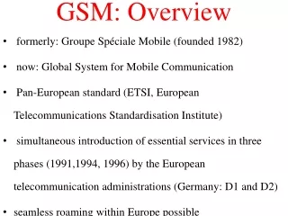
1. Overview of the GSM System The GSM is designed to allow for international roaming. The original vision was that each country will have its own network and to interconnect these networks through gateways. The network interconnections should be transparent to users.
The basic network module is called: Public Land Mobile Network (PLMN). It works more or less like an area code. Small countries are covered with one PLMN. Larger countries required two or more PLMN's.
The GSM is the "sum" of all PLMN's. The GSM is designed to allow for international roaming. The original vision was that each country will have its own network and to interconnect these networks through gateways. The network interconnections should be transparent to users.
The basic network module is called: Public Land Mobile Network (PLMN). It works more or less like an area code. Small countries are covered with one PLMN. Larger countries required two or more PLMN's.
The GSM is the "sum" of all PLMN's.
2. Hierarchy of Areas Apart hierarchal structure of the different network components, the GSM also has an area hierarchy. At the top level is the GSM area, which consists of all areas served by GSM. At the lowest level is a cell (or a sector in a cell) served by a single BTS.
The full hierarchy consists of: Cell, Location area, MSC service area, PLMN area, GSM
Area's definition is necessary to keep proper track of the mobile home location and to control and facilitate mobility functions such as paging and location update.
Each cell is identified by a unique number called: "The Location Area Identification (LAI)". The unique number indicates the country, the network and the specific cell within the network.. Apart hierarchal structure of the different network components, the GSM also has an area hierarchy. At the top level is the GSM area, which consists of all areas served by GSM. At the lowest level is a cell (or a sector in a cell) served by a single BTS.
The full hierarchy consists of: Cell, Location area, MSC service area, PLMN area, GSM
Area's definition is necessary to keep proper track of the mobile home location and to control and facilitate mobility functions such as paging and location update.
Each cell is identified by a unique number called: "The Location Area Identification (LAI)". The unique number indicates the country, the network and the specific cell within the network..
3. The MSC Area The MSC area consists of one MSC and several BSS's
The MSC provides the external interface, either directly or through a Gateway MSC
Each MSC is connected to a Visitor Location Registry (VLR)
The MSC also has access to a Home Location Registry (HLR) and Equipment Identification Registry (EIR) The MSC is the main center of communications. Other elements in the network (BST and BSC) perform minor functions compared to the MSC.
While an MS physically communicates with the MSC through a BTS and BSC, in many scenarios, it functionally communicates directly with the MSC.
Each MSC is connected to a single VLR. All calls that belong to the MSC are monitored and registered in the same VLR. In many cases, the VLR is physically part of the MSC.
Functionally, an HLR should be able to contact any HLR in the system to monitor and verify the records of a visiting MS.
There is no specific association between an MSC and an HLR The MSC is the main center of communications. Other elements in the network (BST and BSC) perform minor functions compared to the MSC.
While an MS physically communicates with the MSC through a BTS and BSC, in many scenarios, it functionally communicates directly with the MSC.
Each MSC is connected to a single VLR. All calls that belong to the MSC are monitored and registered in the same VLR. In many cases, the VLR is physically part of the MSC.
Functionally, an HLR should be able to contact any HLR in the system to monitor and verify the records of a visiting MS.
There is no specific association between an MSC and an HLR
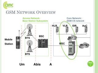
4. The GSM Network Model Communications among the different entities of the GSM system are specified as standard interfaces. The GSM network model identifies the different network elements and their interfaces.
Each interface is labeled by a letter
Each letter interface indicates a complete set of physical connections and signaling protocol Communications among the different entities of the GSM system are specified as standard interfaces. The GSM network model identifies the different network elements and their interfaces.
Each interface is labeled by a letter
Each letter interface indicates a complete set of physical connections and signaling protocol
5. The GSM System Hierarchy This slide shows the network hierarchy.
The PLMN is divided among MSC's
The MSC serves several BSS's
The BSS consists of one TRAU, one BSC and several BTS
A BTS serves a cell and communicates with several MS'sclusters of base stations called BSSThis slide shows the network hierarchy.
The PLMN is divided among MSC's
The MSC serves several BSS's
The BSS consists of one TRAU, one BSC and several BTS
A BTS serves a cell and communicates with several MS'sclusters of base stations called BSS
6. The TRAU Unit The Transcoding Rate and Adaptation Unit (TRAU) is typically located between the MSC and BSC.
It could also be placed between the BSC and the BTS's
It converts the 64 kbps PCM-speech into 16 kbps compressed speech [13 kbps speech + 3 kbps overhead]
It uses speech vocoding technique.
There is an equivalent unit in the Mobile Station (MS) The Transcoding Rate and Adaptation Unit (TRAU) is essentially a voice coder-decode (vocoder).
There is a similar vocoder in the MS. It operates on the same principles.
Voice is transmitted digitally throughout the GSM system but ther are two format:
From TRAU to MSC and any other network interface, the digital speech has the standard 64 kbps Pulse Code Modulation (PCM) format.
From the TRAU to the BTS the voice is compressed into 16 kbps.
The 16 kbps includes 3 kbps overhead. The net rate of the compressed speech is 13 kbps.
The Transcoding Rate and Adaptation Unit (TRAU) is essentially a voice coder-decode (vocoder).
There is a similar vocoder in the MS. It operates on the same principles.
Voice is transmitted digitally throughout the GSM system but ther are two format:
From TRAU to MSC and any other network interface, the digital speech has the standard 64 kbps Pulse Code Modulation (PCM) format.
From the TRAU to the BTS the voice is compressed into 16 kbps.
The 16 kbps includes 3 kbps overhead. The net rate of the compressed speech is 13 kbps.
7. The TRAU Unit (cont.) The TRAU unit could be physically located with the MSC to save transmitting 64 kbps/speech connection
If the connection is "data connection" (rather than speech), the unit is turned off
In the MS, the same vocoding technique is used to convert analog signal into digital speech at 13 kbps (full rate)
The unit could also operate at 6.5 kbps (half rate) The TRAU unit is functionally assigned to the BSC. Physically, however, it is often located with the MSC to shorted the distance traveled at 64 kbps.
The typical configuration of the TRAU is to be placed between the MSC and the BSC. It is possible, however, to find TRAU placed between the BSC and the BST.
Currently, all TRAU units compress the speech down to 13 kbps. This is known as a "Full Rate" speech channel. The GSM system, however, includes provisions that allow for "Half Rate" speech of 6.5 kbps. These provisions are made in anticipation of further developments in the vocoder technology.
The TRAU unit does not work on data. When the traffic channel carries data, the TRAU unit is turned off. The TRAU unit is functionally assigned to the BSC. Physically, however, it is often located with the MSC to shorted the distance traveled at 64 kbps.
The typical configuration of the TRAU is to be placed between the MSC and the BSC. It is possible, however, to find TRAU placed between the BSC and the BST.
Currently, all TRAU units compress the speech down to 13 kbps. This is known as a "Full Rate" speech channel. The GSM system, however, includes provisions that allow for "Half Rate" speech of 6.5 kbps. These provisions are made in anticipation of further developments in the vocoder technology.
The TRAU unit does not work on data. When the traffic channel carries data, the TRAU unit is turned off.
8. GSM Typical Voice Connection This slide illustrates a typical voice connection through the GSM system.
On the air interface, the coded digital voice is transmitted at a rate of 22.8 kbps. That is almost 75% of coding overhead with respect to the compressed speech full rate of 13 kbps.
At the RTS, the speech digits are decoded and the 13 kbps are recovered. 3 kbps of signaling overhead is then added to the speech to form the 16 kbps stream.
The 16 kbps signals goes from the BTS to the BSC and then to the TRAU at the MSC site.
The TRAU de-compress the signal and recovers the standard 64 kbps PCM speech signal.
The MSC provides an interface to the digital hierarchy of the PSTN (where 64 kbps is the basic switching unit). The signal is switched and multiplexed in the PSTN as needed until it reaches its destination at the receiving phone.This slide illustrates a typical voice connection through the GSM system.
On the air interface, the coded digital voice is transmitted at a rate of 22.8 kbps. That is almost 75% of coding overhead with respect to the compressed speech full rate of 13 kbps.
At the RTS, the speech digits are decoded and the 13 kbps are recovered. 3 kbps of signaling overhead is then added to the speech to form the 16 kbps stream.
The 16 kbps signals goes from the BTS to the BSC and then to the TRAU at the MSC site.
The TRAU de-compress the signal and recovers the standard 64 kbps PCM speech signal.
The MSC provides an interface to the digital hierarchy of the PSTN (where 64 kbps is the basic switching unit). The signal is switched and multiplexed in the PSTN as needed until it reaches its destination at the receiving phone.
9. The IWF is a generic term that applies to interface units at the MSC.
In a typical data call, the system establishes a point to point connection between the handset and the IWF. Within the cellular network, the call is treated as a circuit switched call.
The IWF provides a software/hardware protocol translation. The traffic on the data side of the IWF is determined by the data protocol.
It should be mentioned that in the 3G system, the call may be treated differently within the cellular network segment. Many proposals are now being in the development phase.The IWF is a generic term that applies to interface units at the MSC.
In a typical data call, the system establishes a point to point connection between the handset and the IWF. Within the cellular network, the call is treated as a circuit switched call.
The IWF provides a software/hardware protocol translation. The traffic on the data side of the IWF is determined by the data protocol.
It should be mentioned that in the 3G system, the call may be treated differently within the cellular network segment. Many proposals are now being in the development phase.
10. GPRS (Generalized Packet Radio Service) was the first major evolution of the basic GSM system.
GPRS introduced the packet mode in a comprehensive way.
The air interface of GSM remains more or less intact, but instead of the normal mode of allowing the circuit switched users to use a time slot continuously for the duration of the call, packet users will be given a time slot for a limited predetermined time.
The major network structural evolution was to modify the BSC and allow it to determine if the call is circuit switched (CS) or packet switched (PS).
If the call is CS it proceeds as usual towards the MSC/VLR.
If the call is PS, then it is directed towards a servicing node called "Serving GPRS Support Node" (SGSN), which is designed to handle packet traffic.
The call interfaces with public data networks (PDN) through a gateway known as "Gateway GPRS Support Node" (GGSN). GPRS (Generalized Packet Radio Service) was the first major evolution of the basic GSM system.
GPRS introduced the packet mode in a comprehensive way.
The air interface of GSM remains more or less intact, but instead of the normal mode of allowing the circuit switched users to use a time slot continuously for the duration of the call, packet users will be given a time slot for a limited predetermined time.
The major network structural evolution was to modify the BSC and allow it to determine if the call is circuit switched (CS) or packet switched (PS).
If the call is CS it proceeds as usual towards the MSC/VLR.
If the call is PS, then it is directed towards a servicing node called "Serving GPRS Support Node" (SGSN), which is designed to handle packet traffic.
The call interfaces with public data networks (PDN) through a gateway known as "Gateway GPRS Support Node" (GGSN).
11. GSM Air Interface
12. Base Transceiver Station Typically the Base Transceiver Stations exist in clusters of three (120o sectors). The diameter of the cell is between 300 m and 35 km).
Each BTS has a different Cell Identity (CI)
Some BTS could serve what is called "Umbrella Cells" to serve fast mobile units. The widely used mode of deployment is the 120-degree sectored antennas.
In this configuration, each cell is split into 3 sectors and is served by a separate BTS.
Sectors within the cells are assigned different carrier frequencies.
The GSM system also supports a cell hierarchy in which small cells are overlapped by larger cells called "umbrella Cells".
The umbrella cell has its own set of carriers that do not interfere with the carriers assigned to the overlapped small cells.
A call is assigned to the umbrella cell when it has higher level of mobility. For example, a cell phone in a car would cross several small cells during a call. Instead of invoking many hand-off, such call can be assigned to the larger cell. The widely used mode of deployment is the 120-degree sectored antennas.
In this configuration, each cell is split into 3 sectors and is served by a separate BTS.
Sectors within the cells are assigned different carrier frequencies.
The GSM system also supports a cell hierarchy in which small cells are overlapped by larger cells called "umbrella Cells".
The umbrella cell has its own set of carriers that do not interfere with the carriers assigned to the overlapped small cells.
A call is assigned to the umbrella cell when it has higher level of mobility. For example, a cell phone in a car would cross several small cells during a call. Instead of invoking many hand-off, such call can be assigned to the larger cell.
13. Base Transceiver Station (cont.) Each BTS has several Transmit/Receive (Tx/Rx) units.
The maximum number of Tx/Rx units per BTS is 16
The BTS also has control circuits for operation, management and clock distribution The last part of the infrastructure is the base station (known as Base Transceiver System, BTS)
A BTS consists of several Transmit/Receive units (Tx/Rx) working in parallel and operating on different carrier frequencies.
The maximum number of Tx/Rx per BTS is 16
The Tx/Rx units share a common broadband front-end RF section including an antenna distribution systems.
The received signals are separated at the IF-level where each unit tunes to its designated carrier.
Since the most common frequency re-use pattern in GSM is the 4-cell structure, carrier frequencies of different Tx/Rx units within the same BTS are separated by at least 4x200 = 800 kHzThe last part of the infrastructure is the base station (known as Base Transceiver System, BTS)
A BTS consists of several Transmit/Receive units (Tx/Rx) working in parallel and operating on different carrier frequencies.
The maximum number of Tx/Rx per BTS is 16
The Tx/Rx units share a common broadband front-end RF section including an antenna distribution systems.
The received signals are separated at the IF-level where each unit tunes to its designated carrier.
Since the most common frequency re-use pattern in GSM is the 4-cell structure, carrier frequencies of different Tx/Rx units within the same BTS are separated by at least 4x200 = 800 kHz
14. The Transmit/Receive Module The Tx/Rx unit consists of five sections:
Data interface unit to provide interface with the BSC
Baseband signal processing unit
Frequency Hopping and Radio frequency control module
Tx/Rx RF section
Control unit This slide illustrates some details of the Tx/Rx unit structure.
The first block to the right is an interface unit, where any overhead bits from the A-bis interface is stripped or added from or to the RF data.
Coding, interleaving, equalization and modulation functions are performed in the signal processing block.
Slow frequency hopping can be performed at baseband or using a frequency synthesizer. The former (baseband frequency hopping) is more popular due to its relative simplicity.
Diversity is almost mandatory in GSM base station receivers. Typically the Tx/Rx units share two antennas, one is used for transmission but both are used for diversity reception.
It should be pointed out that the Tx/Rx unit does not have the intelligent to select a time slot for a specific MS. Such a decision is made by the BSC. This slide illustrates some details of the Tx/Rx unit structure.
The first block to the right is an interface unit, where any overhead bits from the A-bis interface is stripped or added from or to the RF data.
Coding, interleaving, equalization and modulation functions are performed in the signal processing block.
Slow frequency hopping can be performed at baseband or using a frequency synthesizer. The former (baseband frequency hopping) is more popular due to its relative simplicity.
Diversity is almost mandatory in GSM base station receivers. Typically the Tx/Rx units share two antennas, one is used for transmission but both are used for diversity reception.
It should be pointed out that the Tx/Rx unit does not have the intelligent to select a time slot for a specific MS. Such a decision is made by the BSC.
15. The Mobile Station (MS) The user identity is separate from the equipment identity.
The user information is stored in the SIM (Subscriber Information Module). Also known as the smart card
Different processing blocks are used to process the voice/data This slide illustrates the basic processing blocks of the MS.
At the bottom there is a smart card module. This section accept a card that contains authentication and account information about the user. The card also record and track the calls.
Above the smart card is the control plane, where various control and clock distribution functions take place.
The communication blocks are shown on top of the control circuit. These are typical signal processing blocks in wireless systems:
Forward Error Correction Coding (FEC). Convolutional coding.
Two levels of interleaving
Ciphering for security
GMSK modulation
RF transceiver.This slide illustrates the basic processing blocks of the MS.
At the bottom there is a smart card module. This section accept a card that contains authentication and account information about the user. The card also record and track the calls.
Above the smart card is the control plane, where various control and clock distribution functions take place.
The communication blocks are shown on top of the control circuit. These are typical signal processing blocks in wireless systems:
Forward Error Correction Coding (FEC). Convolutional coding.
Two levels of interleaving
Ciphering for security
GMSK modulation
RF transceiver.
16. Time-Frequency Plan GSM is a Time Division Multiple Access / Frequency Division Duplexing TDMA/FDD.
The available bandwidth consists of two segments. One for the mobiles to transmit on [the lower frequency segment] and the other is for the base stations to transmit on [the higher frequency segment].
The two segments are divided into 200 kHz frequency carriers and each carrier in the lower segment is paired with its counterpart in the upper segment.
The frequency spacing between two paired carriers is either 45 MHz (in the cellular band) or 80 MHz (in the PCS band)
Each pair of carriers serves up to 8 mobiles. The 8 mobiles share the same carrier by transmitting in different time slots. Therefore, the time is divided into frames with 8 time slots per frame.
An active mobile is assigned one time slot on the low frequency carriers to transmit in and another time slot on the upper frequency carrier to receive on.
For a given mobile, the transmit and receive time slots are offset by two slot positions GSM is a Time Division Multiple Access / Frequency Division Duplexing TDMA/FDD.
The available bandwidth consists of two segments. One for the mobiles to transmit on [the lower frequency segment] and the other is for the base stations to transmit on [the higher frequency segment].
The two segments are divided into 200 kHz frequency carriers and each carrier in the lower segment is paired with its counterpart in the upper segment.
The frequency spacing between two paired carriers is either 45 MHz (in the cellular band) or 80 MHz (in the PCS band)
Each pair of carriers serves up to 8 mobiles. The 8 mobiles share the same carrier by transmitting in different time slots. Therefore, the time is divided into frames with 8 time slots per frame.
An active mobile is assigned one time slot on the low frequency carriers to transmit in and another time slot on the upper frequency carrier to receive on.
For a given mobile, the transmit and receive time slots are offset by two slot positions
17. Time-Frequency Plan (cont.) In most GSM deployments, the frequency reuse pattern is a 4-cell pattern as shown in the slide. The total available bandwidth is assigned to a cluster of 4-cells (A, B, C and D).
Adjacent frequencies are not assigned in the same cell. In fact, within a cell, the frequency spacing among carriers is multiples of 4x200 kHz (800 kHz).
The ABCD pattern is repeated throughout the service area. The repeat scheme ensures that cells that are using the same frequency set have the maximum possible distance separation. This reduces the co-channel interference.
Since each cell (or sector in a cell) can have up to 16 transceiver units and since each transceiver supports up to 8 voice circuits, then the maximum number of voice circuits that may be simultaneously supported in a sector is 128. In most GSM deployments, the frequency reuse pattern is a 4-cell pattern as shown in the slide. The total available bandwidth is assigned to a cluster of 4-cells (A, B, C and D).
Adjacent frequencies are not assigned in the same cell. In fact, within a cell, the frequency spacing among carriers is multiples of 4x200 kHz (800 kHz).
The ABCD pattern is repeated throughout the service area. The repeat scheme ensures that cells that are using the same frequency set have the maximum possible distance separation. This reduces the co-channel interference.
Since each cell (or sector in a cell) can have up to 16 transceiver units and since each transceiver supports up to 8 voice circuits, then the maximum number of voice circuits that may be simultaneously supported in a sector is 128.
18. Frequencies within the Same Cell Each cell operates on several frequencies
The spacing between those frequencies is typically 800 kHz (4x200 kHz)
Each frequency is shared by a maximum of 8 mobiles
One of the frequency is designated to carry control and signaling signals. That frequency is known as the "control Frequency"
The control frequency uses only one time slot (typically the first) for control and signaling. The rest of the slots carry user traffic (maximum of 7 mobiles)
Usually the control frequency is transmitted with higher power.
The control frequency plays crucial role in initial synchronization and mobile registrationEach cell operates on several frequencies
The spacing between those frequencies is typically 800 kHz (4x200 kHz)
Each frequency is shared by a maximum of 8 mobiles
One of the frequency is designated to carry control and signaling signals. That frequency is known as the "control Frequency"
The control frequency uses only one time slot (typically the first) for control and signaling. The rest of the slots carry user traffic (maximum of 7 mobiles)
Usually the control frequency is transmitted with higher power.
The control frequency plays crucial role in initial synchronization and mobile registration
20. The TDMA Frame The TDMA frame consists of 8 time slots. The total duration is 4.615 ms.
A voice circuit consists of a pair of time slots. One time slot for the mobile to transmit on (on the lower carrier frequency), and the other time slot for the base station to transmit on (on the higher carrier frequency).
In order to simplify the RF circuitry, the transmit and receive time slots are offset by two time slots. Therefore, the mobile does not transmit and receive at the same time.The TDMA frame consists of 8 time slots. The total duration is 4.615 ms.
A voice circuit consists of a pair of time slots. One time slot for the mobile to transmit on (on the lower carrier frequency), and the other time slot for the base station to transmit on (on the higher carrier frequency).
In order to simplify the RF circuitry, the transmit and receive time slots are offset by two time slots. Therefore, the mobile does not transmit and receive at the same time.
22. The Power-Time Template This slide illustrates the power-time template of the normal traffic burst.
The nominal length of the burst is 577 ms, which corresponds to 156.26 symbols (bits).
The useable time is only 542.8 ms (148 bits). The rest of the time is used for the amplifier's ramping up and ramping down.
More precisely, only 147 bits are transmitted. One half of a bit is used on each side of the burst to allow for further power level stabilization.This slide illustrates the power-time template of the normal traffic burst.
The nominal length of the burst is 577 ms, which corresponds to 156.26 symbols (bits).
The useable time is only 542.8 ms (148 bits). The rest of the time is used for the amplifier's ramping up and ramping down.
More precisely, only 147 bits are transmitted. One half of a bit is used on each side of the burst to allow for further power level stabilization.
23. The Guard Period During initialization, the propagation delay between the MS and base station is estimated and the mobile is ordered to either advance or retard its transmission time to avoid overlaps with other mobiles operating on adjacent time slots.
The guard time by itself is not enough to guarantee non-overlapping conditions. The 8.25 bit guard time compensates for differential delay in cells smaller than 9.3 km in radius. Remember that cells could be as large as 35 km.
The time alignment procedure during initialization reduces the differential delays among mobiles, and under this condition, the relatively small guard time on the normal burst (8.25 bits) is good enough. During initialization, the propagation delay between the MS and base station is estimated and the mobile is ordered to either advance or retard its transmission time to avoid overlaps with other mobiles operating on adjacent time slots.
The guard time by itself is not enough to guarantee non-overlapping conditions. The 8.25 bit guard time compensates for differential delay in cells smaller than 9.3 km in radius. Remember that cells could be as large as 35 km.
The time alignment procedure during initialization reduces the differential delays among mobiles, and under this condition, the relatively small guard time on the normal burst (8.25 bits) is good enough.
24. Bursts from Different Users This slide shows transmission bursts of three mobiles in the same working on three adjacent time slots.
Notice that the guard time of one mobile overlaps with the ramping-up time of the next mobile. Therefore, there is little time wasted between consecutive mobile transmissions.
This picture indicates the the gap size is determined mainly by the time its takes the amplifier to ramp-up and down and not necessarily by the differential propagation delay among mobiles.
One should keep in mind that the three bursts shown could have different amplitudes, depending on the mobile locations.This slide shows transmission bursts of three mobiles in the same working on three adjacent time slots.
Notice that the guard time of one mobile overlaps with the ramping-up time of the next mobile. Therefore, there is little time wasted between consecutive mobile transmissions.
This picture indicates the the gap size is determined mainly by the time its takes the amplifier to ramp-up and down and not necessarily by the differential propagation delay among mobiles.
One should keep in mind that the three bursts shown could have different amplitudes, depending on the mobile locations.
25. Frame Hierarchy The physical channel in the GSM system is one transmission slot on a carrier. The length of the transmission slot is 577 ?sec.
The next level in the frame hierarchy is the TDMA frame, which is 4.615 ms long and is made up of 8 transmission slots as shown.
In a cell (or a sector), there is one frequency carrier specialized in signaling, control and broadcast. The framing on that carrier is different from the framing on all other data carriers.
On the "data" carriers, the TDMA frames are grouped into a larger frame called the 26-multi-frames. As the name indicates, each one of these frame consists of 26 TDMA frames and lasts 120 ms.
On the "signaling" carrier, 51 TDMA frames are grouped to form the 235.35 ms frame known as: 51-multi-frame.
The next level up in the hierarchy is the "super frame", whose length is 6.12 s and is made of [51 x 26-multi-frames] = [26 x 51-multi-frames].
2048 "super frames" make one "hyper-frame". Hyper frames are used for security related functions. The physical channel in the GSM system is one transmission slot on a carrier. The length of the transmission slot is 577 ?sec.
The next level in the frame hierarchy is the TDMA frame, which is 4.615 ms long and is made up of 8 transmission slots as shown.
In a cell (or a sector), there is one frequency carrier specialized in signaling, control and broadcast. The framing on that carrier is different from the framing on all other data carriers.
On the "data" carriers, the TDMA frames are grouped into a larger frame called the 26-multi-frames. As the name indicates, each one of these frame consists of 26 TDMA frames and lasts 120 ms.
On the "signaling" carrier, 51 TDMA frames are grouped to form the 235.35 ms frame known as: 51-multi-frame.
The next level up in the hierarchy is the "super frame", whose length is 6.12 s and is made of [51 x 26-multi-frames] = [26 x 51-multi-frames].
2048 "super frames" make one "hyper-frame". Hyper frames are used for security related functions.
26. Air Interface Channels
27. Logical Channels This is a more accurate classification of the different logical channels.
Traffic channels are labeled as "Full" or "Half".
Full channel means a dedicated time slot in every TDMA frame, while Half channel means one time slot every other TDMA frame
The control channel could also work on full or fractional basis. For example, during some signaling procedures, a dedicated control channel could be assigned on a 1/8th basis, which means that the mobile can use the channel once every 8 TDMA frames.This is a more accurate classification of the different logical channels.
Traffic channels are labeled as "Full" or "Half".
Full channel means a dedicated time slot in every TDMA frame, while Half channel means one time slot every other TDMA frame
The control channel could also work on full or fractional basis. For example, during some signaling procedures, a dedicated control channel could be assigned on a 1/8th basis, which means that the mobile can use the channel once every 8 TDMA frames.
28. Different Transmission Bursts There are "four" different transmission bursts in the GSM system: normal, random access, frequency correction and synchronization.
Frequency correction and synchronization bursts are broadcast, one-way bursts (from base to mobiles). These are transmitted periodically on the "signaling" carrier as part of the BCCH. Their purpose is to guide new mobiles in their initial synchronization and system acquisition procedure.
The random access burst is distinguished with its long silence gap. This is necessary for initial access where the exact location and timing of the mobile is unknown. There are "four" different transmission bursts in the GSM system: normal, random access, frequency correction and synchronization.
Frequency correction and synchronization bursts are broadcast, one-way bursts (from base to mobiles). These are transmitted periodically on the "signaling" carrier as part of the BCCH. Their purpose is to guide new mobiles in their initial synchronization and system acquisition procedure.
The random access burst is distinguished with its long silence gap. This is necessary for initial access where the exact location and timing of the mobile is unknown.
29. The Frequency Correction Burst The Frequency Correction Burst is broadcast periodically by the base station. It is one way burst.
This burst allows the mobiles to detect the carrier which carries the system information and broadcast messages and to also allow the mobile to correct their local carriers to that of the base station.
The burst does not carry coded data. The body of the burst is simply made of long sequence of zeros (142 zeros). The string of zeros produces a spectral line in the spectrum of the broadcast channel and makes it easy to detect the channel and tune the local carriers.The Frequency Correction Burst is broadcast periodically by the base station. It is one way burst.
This burst allows the mobiles to detect the carrier which carries the system information and broadcast messages and to also allow the mobile to correct their local carriers to that of the base station.
The burst does not carry coded data. The body of the burst is simply made of long sequence of zeros (142 zeros). The string of zeros produces a spectral line in the spectrum of the broadcast channel and makes it easy to detect the channel and tune the local carriers.
30. The Synchronization Burst The synchronization burst always follows the frequency burst in the signaling frame. Its purpose is to complete the synchronization process and convey some important system parameters to the mobile.
Its structure is very similar to the normal burst. The differences are: (1) longer training sequence and (2) shorter data field.The synchronization burst always follows the frequency burst in the signaling frame. Its purpose is to complete the synchronization process and convey some important system parameters to the mobile.
Its structure is very similar to the normal burst. The differences are: (1) longer training sequence and (2) shorter data field.
31. The Normal Traffic Burst The normal burst is 148-bit long followed with 8.25-bit of silence gap.
The silence gap allows the ON-transmitter to ramp-down and the next transmitter to ramp-up.
During the 148-bit active interval, the transmitter power level is stable.
The active interval starts with a 3-bit trail and ends with the same 3-bit trail. The purpose of the trail bits is to mark the start and end of the bursts.
The data consists of two, 57-bit fields separated by a known training sequence. Normally, the first 57-bit data field carries voice data from one speech frame, and the second 57-bit field carries voice data from the next speech frame. This is part of the interleaving strategy as explained later.
The one-bit fields separating the data fields from the training sequence are called the stealing flags. They are used when urgent signaling must be exchanged between the base and mobile. In such cases, one or both of the flags are set to "1" indicating that the speech data has been replaced by signaling message.
The training sequence in the middle is used to estimate the channel status. The normal burst is 148-bit long followed with 8.25-bit of silence gap.
The silence gap allows the ON-transmitter to ramp-down and the next transmitter to ramp-up.
During the 148-bit active interval, the transmitter power level is stable.
The active interval starts with a 3-bit trail and ends with the same 3-bit trail. The purpose of the trail bits is to mark the start and end of the bursts.
The data consists of two, 57-bit fields separated by a known training sequence. Normally, the first 57-bit data field carries voice data from one speech frame, and the second 57-bit field carries voice data from the next speech frame. This is part of the interleaving strategy as explained later.
The one-bit fields separating the data fields from the training sequence are called the stealing flags. They are used when urgent signaling must be exchanged between the base and mobile. In such cases, one or both of the flags are set to "1" indicating that the speech data has been replaced by signaling message.
The training sequence in the middle is used to estimate the channel status.
32. The Training Sequence (Mid-Amble) The training sequence is a 26-bit known pattern. During the initial synchronization phase, the synchronization burst uses a longer version of the training pattern and the mobile learns which training sequence is being used in the cell.
The 26-bit sequence is in fact only 16-bit long. The 16 bits are augmented by repeating the first 5 bits at the end and repeating the last 5 bits at the start. This arrangement emulates a continuous (rather than discontinued) 16-bit sequence.
Since the training sequence is known, both of the base station and the mobile use it to estimate the channel impairments. This is accomplished at either end of the link, by correlating the received sequence with a local version. The results of the correlation provide the channel signature. The training sequence is a 26-bit known pattern. During the initial synchronization phase, the synchronization burst uses a longer version of the training pattern and the mobile learns which training sequence is being used in the cell.
The 26-bit sequence is in fact only 16-bit long. The 16 bits are augmented by repeating the first 5 bits at the end and repeating the last 5 bits at the start. This arrangement emulates a continuous (rather than discontinued) 16-bit sequence.
Since the training sequence is known, both of the base station and the mobile use it to estimate the channel impairments. This is accomplished at either end of the link, by correlating the received sequence with a local version. The results of the correlation provide the channel signature.
33. The Training Sequence (cont.) The training sequence is used as a "color code" among neighboring cells.
A MS talking to a cell uses the training sequence of that cell in the transmitted and received bursts. Since all cells within a "listening distance" from the MS use different training codes, there is very little chance that the MS will attempt to decode messages of other cells, even when their signal is temporarily larger than the desired signal.The training sequence is used as a "color code" among neighboring cells.
A MS talking to a cell uses the training sequence of that cell in the transmitted and received bursts. Since all cells within a "listening distance" from the MS use different training codes, there is very little chance that the MS will attempt to decode messages of other cells, even when their signal is temporarily larger than the desired signal.
34. The Random Access Burst The Random Access Burst is used by the mobile to access the system when it does not have a traffic channel.
The design of this burst reflects two facts:
The mobile location is not known and therefore "timing correction" is not possible.
There is no sustained connection and therefore initial synchronization must be established at the base station
The first fact is compensated for by providing a long gap (68.25 bit compared to only 8.25 bit in the normal burst)
Long synchronization sequence (41 bit compared to the 26-bit training sequence in the normal burst).
The Random Access Burst is used by the mobile to access the system when it does not have a traffic channel.
The design of this burst reflects two facts:
The mobile location is not known and therefore "timing correction" is not possible.
There is no sustained connection and therefore initial synchronization must be established at the base station
The first fact is compensated for by providing a long gap (68.25 bit compared to only 8.25 bit in the normal burst)
Long synchronization sequence (41 bit compared to the 26-bit training sequence in the normal burst).
35. Frequency Hopping Frequency hopping is an option available GSM operators. It is a defense mechanism against being stuck in a bad spot. In a normal operation of a wireless system, some links could be subjected to excessive interference or bad reception. One possible technique to remedy such situation is to invoke in-cell handoff (explained later). Another technique is to employ frequency hopping.
When FH is employed, a link operates on a given frequency for a while, then jumps onto a different frequency. The hopping pattern is pre-determined and known to all users in the cell
All 8 users on the carrier jump at the same time to the next carrier.
All hopping patterns are predetermined in a given cell.
Frequency hopping is an option available GSM operators. It is a defense mechanism against being stuck in a bad spot. In a normal operation of a wireless system, some links could be subjected to excessive interference or bad reception. One possible technique to remedy such situation is to invoke in-cell handoff (explained later). Another technique is to employ frequency hopping.
When FH is employed, a link operates on a given frequency for a while, then jumps onto a different frequency. The hopping pattern is pre-determined and known to all users in the cell
All 8 users on the carrier jump at the same time to the next carrier.
All hopping patterns are predetermined in a given cell.
36. Frequency Hopping Example This slide illustrates an example of frequency hopping when the number of frequencies in the cell is 3. The hopping pattern is simply : F1 F2 F3 F1 F2 �etc.
Notice the followings:
All 8 users on a carrier follow the same pattern.
The base station and mobile station hop together keeping the spacing between the transmit and receive frequencies constant.
The mobile transmitter slot is delayed from the base transmitter slot by 2 slots, and the base transmitter occurs 4 time slots after the mobile transmitter slot
The time spacing between the instant when the mobile stops transmitting and the base starts transmitting is used by the mobile to tune its receiver to other frequencies and listen to adjacent cells. This is a necessary function for the handover.This slide illustrates an example of frequency hopping when the number of frequencies in the cell is 3. The hopping pattern is simply : F1 F2 F3 F1 F2 �etc.
Notice the followings:
All 8 users on a carrier follow the same pattern.
The base station and mobile station hop together keeping the spacing between the transmit and receive frequencies constant.
The mobile transmitter slot is delayed from the base transmitter slot by 2 slots, and the base transmitter occurs 4 time slots after the mobile transmitter slot
The time spacing between the instant when the mobile stops transmitting and the base starts transmitting is used by the mobile to tune its receiver to other frequencies and listen to adjacent cells. This is a necessary function for the handover.
37. Power Control