Troubleshooting and Automation of TPAC1.1 Boards and Laser Tests
80 likes | 203 Views
This report outlines the testing and troubleshooting of the TPAC1.1 boards after receiving ten units from Paul. While nine boards operated correctly, one did not respond from one of the DAC banks, necessitating a return for investigation. Common issues like power-ground shorts were found in multiple chips, likely due to bonding problems. Moreover, various automated scripts and Labview setups were implemented for laser testing, pixel scans, and data plotting. The process aims to improve testing reliability and ensure accurate measurements moving forward, documented fully on the "Spider Wiki."

Troubleshooting and Automation of TPAC1.1 Boards and Laser Tests
E N D
Presentation Transcript
TPAC1.1 Jamie Crooks
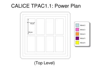
First Batch • Four boards • Received 10 at last meeting from Paul • Tested before bonding • 9 boards operated correctly, testing… • Operating current • Board ID • PCB temperature • Probed voltages at all power jumpers • DAC references initial value and read/write • 1 board showed no response from one of the DAC banks • Returned to IC for investigation • Four chips (12u epi, with DPW) • Three had a power-ground short! • One had sensible power consumption • Most likely a bonding problem • New bond program in use for the larger bond pads • Inspection under microscope shows no obviuos evidence as before, but some occasional material deposits on scribe lane • Bond program will be modified and a chip reworked to test
Very First Tests (#32) • Power on • Sensible current • Including J1 fitted promising for the VDD2V5dig bug • SensorLoadV1.1 • See bit errors in columns 2471 • Almost certainly marginal timing on clock edges through up-rated inverter • Monostable test structure • Working correctly • Shows that I12IOUTBIAS bug fixed
TPAC1.0 Jamie Crooks On behalf of Barnaby Levin & Michael Lynch
Summer Students • Bulk pixel scans • Perl scripts automate… • “runStart” commands • Movement of X/Y stage • Laser parameters • Root programs automate • Function fitting to threshold scans • Data plotting • Analog test-pixel scans • Labview automates • Acquisition of measurements from LeCroy scope • Movement of X/Y stage • Laser parameters • Root programs automate • Data plotting • Laser reliability • Fully documented on “Spider Wiki” • Results • Flow charts • Software documentation • Source code
Test pixel scans • 2x2um laser • 2um steps • Two runs • Something crashed • Laser intensity different after restart • Hence the different peaks! • Will repeat • This sensor • Non-DPW sensor • 5um EPI sensor
Laser uniformity 1: Stop Any Software Running The Laser 2: Turn Laser Off At Key 3: Wait For Short Period 4: Turn Laser On At Key 5: Wait For Short Period 6: Fire Laser From Control Box With Desired Settings For Short Period 7: Stop Firing 8: Start Labview, (Will not connect first time) 9: Restart Labview (Software should now be working) 10: Fire Laser From Computer 11: Wait For a Short Period 12: Take Measurements • If laser is turned off/on… • If connection between labview and laser is broken/remade… • Over long periods (weekend)… • Some improvement made by manually firing the laser before re-connecting with labview 1: Stop Any Software Running The Laser 2: Turn Laser Off At Key 3: Wait For Short Period 4: Turn Laser On At Key 5: Wait For Short Period 6: Fire Laser From Control Box With Desired Settings For Short Period 7: Stop Firing 8: Start Labview, (Will not connect first time) 9: Fire Laser From Control Box With Desired Settings For Short Period 10: Stop Firing 11: Restart Labview (Software should now be working) 12: Fire Laser From Computer 13: Wait For a Short Period 14: Take Measurements • Needs more understanding (/fixing?) • Any absolute calibration method must eliminate non-uniformity of this kind