Manil Dev Gomony
An introduction to SDRAM and memory controllers 5kk73. Manil Dev Gomony. Slides contributions: Sven Goossens, Benny Akesson. Outline. Part 1: DRAM and controller basics DRAM architecture and operation Timing constraints DRAM controller Part 2: DRAMs in e mbedded systems


Manil Dev Gomony
E N D
Presentation Transcript
An introduction to SDRAM and memory controllers 5kk73 Manil Dev Gomony Slides contributions: Sven Goossens, Benny Akesson
Outline Part 1: DRAM and controller basics • DRAM architecture and operation • Timing constraints • DRAM controller Part 2: DRAMs in embedded systems • Challenges in sharing DRAMs • Real-time guarantees with DRAMs • Future DRAM architectures and controllers
Memory device “A device that preserves information for retrieval” - Web definition
Semiconductor memories “Semiconductor memory is an electronic data storage device, often used as computer memory, implemented on a semiconductor-based integrated circuit” - Wikipedia definition The main characteristics of semiconductor memory are low cost, high density (bits per chip), and ease of use
Semiconductor memory types RAM (Random Access Memory) • DRAM (Dynamic RAM) • Synchronous DRAM (SDRAM) • SRAM (Static RAM) ROM (Read Only Memory) • Mask ROM, Programmable ROM (PROM), EPROM (Erasable PROM), UVEPROM (Ultra Violet EPROM) NVRAM (Non-Volatile RAM) or Flash memory
Memory hierarchy Processor CPU Registers Registers L1 Cache L1 Cache Access speed Distance from processor L2 Cache L2 Cache Off-chip memory Off-chip memory Secondary memory (Hard disk) Secondary memory Size (capacity)
Memory hierarchy Processor CPU Registers L1 Cache L2 Cache Off-chip memory Secondary memory Credits: J.Leverich, Stanford
SRAM vs DRAM Static Random Access Memory Dynamic Random Access Memory • Bitlines driven by transistors - Fast (10x) • 1 transistor and 1 capacitor vs. 6 transistors • Large (~6-10x) • A bit is stored as charge on the capacitor • Bit cell loses charge over time (read operation and circuit leakage) • Must periodically refresh • Hence the name DynamicRAM Credits: J.Leverich, Stanford
SRAM vsDRAM: Summary SRAM is preferable for register files and L1/L2 caches • Fast access • No refreshes • Simpler manufacturing (compatible with logic process) • Lower density (6 transistors per cell) • Higher cost DRAM is preferable for stand-alone memory chips • Much higher capacity • Higher density • Lower cost • DRAM is the main focus in this lecture! Credits: J.Leverich, Stanford
DRAM: Internal architecture Bank 4 Bank 3 Bank 2 Bank 1 Address register Address MS bits Row decoder Memory Array Row Buffer Row Buffer Row Buffer Sense amplifiers (row buffer) LS bits Column decoder Data Bit cells are arranged to form a memory array Multiple arrays are organized as different banks • Typical number of banks are 4, 8 and 16 Sense amplifiers raise the voltage level on the bitlines to read the data out Credits: J.Leverich, Stanford
DRAM: Read access sequence Bank 1 Address MS bits Row decoder Memory Array Row Buffer Address register Row Buffer Sense amplifiers LS bits Column decoder Data Decode row address & drive word-lines Selected bits drive bit-lines • Entire row read Amplify row data Decode column address & select subset of row Send to output Precharge bit-lines for next access Credits: J.Leverich, Stanford
DRAM: Memory access protocol Bank 1 Memory Array 2nRow x 2nColumn n 2n Address Row decoder CAS RAS Row Buffer Row Buffer 2m Sense amplifiers 2m m Column decoder 1 Data To reduce pin count, row and column share same address pins • RAS = Row Address Strobe • CAS = Column Address Strobe Data is accessed by issuing memory commands 5 basic commands • ACTIVATE • READ • WRITE • PRECHARGE • REFRESH Credits: J.Leverich, Stanford
DRAM: Basic operation Addresses (Row 0, Column 0) (Row 0, Column 1) (Row 0, Column 10) (Row 1, Column 0) Commands ACTIVATE Row 0 READ Column 0 READ Column 1 READ Column 10 PRECHARGE Row 0 ACTIVATE Row 1 READ Column 0 Columns Row 0 Row 1 Row address Row decoder Rows Row Buffer Row buffer MISS! Row buffer HIT! Row buffer Row 1 Row 0 Column address Column decoder Data Credits: J.Leverich, Stanford
DRAM: Basic operation (Summary) Access to an “open row” • No need to issue ACTIVATE command • READ/WRITE will access row buffer Access to a “closed row” • If another row is already active, issue PRECHARGE first • Issue ACTIVATE to open a new row • READ/WRITE will access row buffer • Optional: PRECHARGE after READ/WRITEs finished • If PRECHARGE issued Closed-page policy • If not Open-page policy Credits: J.Leverich, Stanford
DRAM: Burst access Each READ/WRITE command can transfer multiple words (8 in DDR3) Observe the number of words transferred in a single clock cycle • Double Data Rate (DDR) Credits: J.Leverich, Stanford
DRAM: Banks Bank 1 Bank 0 Row 0 Row 1 Row Buffer Row Buffer DRAM chips can consist of multiple banks • Address = (Bank x, Row y, Column z) Banks operate independently, but share command, address and data pins • Each bank can have a different row active • Can overlap ACTIVATE and PRECHARGE latencies!(i.e. READ to bank 0 while ACTIVATING bank 1) Bank-level parallelism Credits: J.Leverich, Stanford
DRAM: Bank-level parallelism Enable DRAM access from different banks in parallel • Reduces memory access latency and improves efficiency! Credits: J.Leverich, Stanford
2Gb x8 DDR3 Chip [Micron] Observe the bank organization Credits: J.Leverich, Stanford
2Gb x8 DDR3 Chip [Micron] Observe row width, bi-directional bus and 64 8 data-path Credits: J.Leverich, Stanford
DDR3 SDRAM: Current standard Introduced in 2007 SDRAM Synchronous DRAM (Clocked) • DDR = Double Data Rate • Data transferred on both clock edges • 400 MHz = 800 MT/s • x4, x8, x16 datapath widths • Minimum burst length of 8 • 8 banks • 1Gb, 2Gb, 4Gb capacity
DRAM: Timing Constraints tRAS tRCD tRL tRP CMD NOP NOP NOP DATA ACT RD NOP PRE NOP NOP NOP D1 Dn • tRCD= Row to Column command delay • Time taken by the charge stored in the capacitor cells to reach the sense amps • tRAS= Time between RAS and data restoration in DRAM array (minimum time a row must be open) • tRP= Time to precharge DRAM array Memory controller must respect the physical device characteristics!
DRAM: Timing Constraints There are a bunch of other timing constraints… • tCCD= Time between column commands • tWTR= Write to read delay (bus turaround time) • tCAS= Time between column command and data out • tWR= Time from end of last write to PRECHARGE • tFAW= Four ACTIVATE window (limits current surge) • Maximum number of ACTIVATEs in this window is limited to four • tRC= tRAS+ tRP= Row “cycle” time • Minimum time between accesses to different rows Timing constraints makes performance analysis and memory controller design difficult!
DRAM controller DRAM controller Front-end Back-end Request scheduler Memory map DRAM Address Command Command generator Request scheduler decides which memory request to be selected Memory map translates logical address physical address • Loical address = incoming address • Physical address = (Bank, Row Column) Command generator issues memory commands respecting the physical device characteristics
Request scheduler Many algorithms exist to determine how to schedule memory requests • Prefer requests targeting open rows • Increases number of row buffer hit • Prefer read after read and write after write • Minimize bus turnaround • Always prefer reads, since reads are blocking and writes often posted • Reduce stall cycles of processor
Memory map Memory map Logical addr. Physical addr. 0x10FF00 (2, 510, 128) Memory map decodes logical address to physical address • Physical address is (bank, row, column) • Decoding is done by slicing the bits in the logical address Several memory mapping schemes exist • Continuous, Bank Interleaved
Continuous memory map Map sequential address to columns in row Switch bank when all columns in row are visited Switch row when all banks are visited
Bank-interleaved memory map Maps bursts to different banks in interleaving fashion Active row in a bank is not changed until all columns are visited Bank-interleaved memory map
Memory map generalization Example memory map (1 burst per bank, 2 banks interleaving, 8 words per burst): Logical address: RRR RRRR RRRR RRBB CCCC CCCB CCCW Bit 0 Bit 26 Burst-size Row Bank-offset Example memory:16-bit DDR3-1600 64 MB 8banks 8K rows / bank 1024 columns / row 16 bits / column Bank interleaving Can be done in different ways – choice affects memory efficiency! Continuous and interleaving memory map are just 2 possible memory mapping schemes • In the most general case, an arbitrary set of bits out of the logical address could be used for the row, column and bank address, respectively
Command generator Command generator Decide selection of memory requests Generate SDRAM commands without violating timing constraints
Command generator Different page policies to determine which command to schedule • Close-page policy: Close rows as soon as possible to activate new one faster, i.e, not to waste time to PRECHARGE the open row of the previous request • Open page policy: Keep rows open as long as possible to benefit from locality, i.e., assuming the next request will target the same open row
Open page or Close page? Addresses (Row 0, Column 0) (Row 0, Column 1) (Row 0, Column 10) (Row 1, Column 0) Commands ACTIVATE Row 0 READ Column 0 READ Column 1 READ Column 10 PRECHARGE Row 0 ACTIVATE Row 1 READ Column 0 Columns Row 0 Row 1 Row address Row decoder Rows Row Buffer Row buffer MISS! Row buffer HIT! Row buffer Row 1 Row 0 Column address Column decoder Data Credits: J.Leverich, Stanford
A modern DRAM controller [Altera] Image: Altera
Conclusions (Part 1) SDRAM is used as off-chip high-volume storage • Cheaper, slower than SRAM DRAM timing constraints makes it hard to design memory controller Selection of memory map and command/request sheduling algorithms impacts memory access time and/or efficiency
Outline Part 1: DRAM and controller basics • DRAM architecture and operation • Timing constraints • DRAM controller Part 2: DRAMs in embedded systems • Challenges in sharing DRAMs • Real-time guarantees with DRAMs • Future DRAM architectures and controllers
Trends in embedded systems • Embedded systems get increasingly complex • Increasingly complex applications (more functionality) • Growing number of applications integrated in a device • Requires increased system performance without increasing power • The case of a generic car manufacturer • Typical number of ECUs in a car in 2000 20 • Number of ECUs in Audi A8 Sedan over 80
System-on-Chip (SoC) The resulting complex contemporary platforms are heterogeneous multi-processor systems • Resources in the system are shared to reduce cost
SoC: Video and audio processing system Video Engine Audio Processor Interconnect Host CPU DMA Controller GPU Input processor DRAM LCD Controller Memory controller A.B. Soares et.al., Development of a SoC for Digital Television Set-Top Box: Architecture and System Integration Issues, International Journal of Reconfigurable Computing Volume 2013 DRAM is typically used as shared main memory for cost and reasons
DRAM controller architecture DRAM controller Client 1 Memory map DRAM Client 2 Client 3 Client 4 Bus Command generator Client n Arbiter The arbiter grants memory access to one of the memory clients at a time • Example: Round-Robin, Time Division Multiplexing (TDM) priority-based arbiters
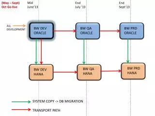
DRAM controller for real-time systems Client 1 DRAM Bounds execution time Client 2 Back-end Client 3 Client 4 Interconnect Client n Arbiter Bounds response time Clients in real-time systems have requirements on latency/bandwidth • A fixed set of memory access parameters such as burst size, page-policy etcin the back-endbounds transaction execution time • Predictablearbiters, such as TDM fixed time slots, Round Robin bounds response time B.Akesson et.al., “Predator: A Predictable SDRAM Memory Controller”, CODES+ISSS, 2007
DRAMs in the market Observe the increase in operating frequency with every generation
DRAMs: Bandwidth vs clock frequency WIDE IO gives much higher bandwidth at lower frequency • Low power consumption
Multi-channel DRAM: WIDE IO Bandwidth demands of future embedded systems > 10 GB/s • Memory power consumption scales up with memory operating frequency “Go parallel” Multi-channel memories • Each channel is an independent memory module with dedicated data and control path • WIDE IO DRAM (4 channels) DRAM Channel 2 DRAM Channel 1 DRAM Channel 2 DRAM Channel 3 DRAM Channel 4 Channel 2 128-bit IO Channel 1 128-bit IO Channel 3 128-bit IO Channel 4 128-bit IO
Multi-channel DRAM controller DRAM controller 1 Back-end Memory client 1 CS Atomizer Channel 2 Channel 1 Arbiter Sequence gen 1 DRAM controller 2 Back-end Memory client 2 CS Atomizer Sequence gen 2 Arbiter M.D.Gomony et.al., “Architecture and Optimal Configuration of a Real-Time Multi-Channel Memory Controller”, DATE, 2012 The Atomizerchops the incoming requests into a number of service units Channel Selector (CS) routes the service units to the different memory channels according to the configuration in the Sequence Genrators
Multi-channel DRAM controller DRAM controller 1 Channel 2 Channel 1 Back-end CS Arbiter Memory client 1 Atomizer DRAM controller 2 Back-end Sequence gen 1 Arbiter Multi-channel memories allow memory requests to be interleaved across multiple memory channels • Reduces access latency
Wide IO memory controller [Cadence] Image: Cadence
Future DRAM: HMC Hybrid Memory Cube (HMC) • 16 memory channels How does the memory controller for HMC look like? Image: Micron, HMC
Conclusions (part 2) DRAMs are shared in multi-processor SoC to reduce cost and to enable communication between the processing elements Sharing DRAMs between multiple memory clients can done using different arbitration algorithms Predictable arbitration and back-end provides real-time guarantees on latency and bandwidth to real-time clients Multi-channel DRAMs allows a memory request to be interleaved across memory channels
Questions? m.d.gomony@tue.nl
References B. Jacob et al., Memory systems: cache, DRAM, disk. Morgan Kaufmann, 2007 B.Akesson et.al., “Predator: A Predictable SDRAM Memory Controller”, CODES+ISSS, 2007 M.D.Gomony et.al., “Architecture and Optimal Configuration of a Real-Time Multi-Channel Memory Controller”, DATE, 2012 http://hybridmemorycube.org/