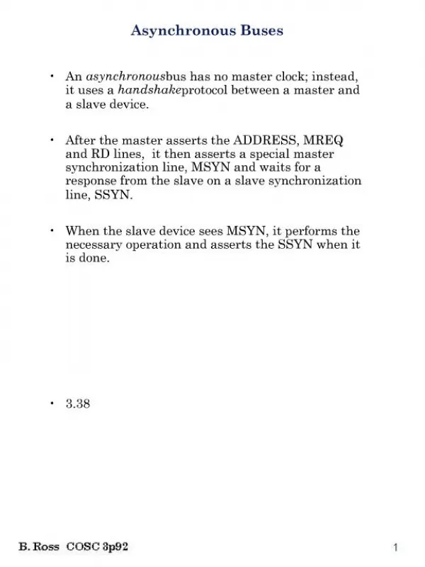
Asynchronous protocol
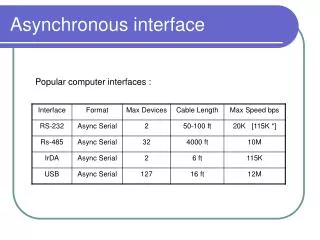
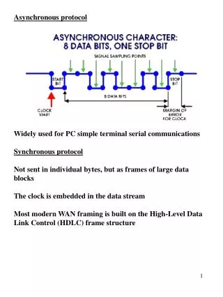
Asynchronous protocol. Widely used for PC simple terminal serial communications Synchronous protocol Not sent in individual bytes, but as frames of large data blocks The clock is embedded in the data stream

Asynchronous protocol
E N D
Presentation Transcript
Asynchronous protocol Widely used for PC simple terminal serial communications Synchronous protocol Not sent in individual bytes, but as frames of large data blocks The clock is embedded in the data stream Most modern WAN framing is built on the High-Level Data Link Control (HDLC) frame structure
HDLC synchronous protocol • The flag is a sequence 01111110 which delimits the start of the frame • The address field is used to indicate or intended receiver of the frame • The control field contains information on the type of frame • user data • supervisory frame - control function • rotating sequence number to check that no frame has been lost. • The "payload" of the frame is the data field • Following the data field are two bytes comprising the Cyclic Redundancy Check(CRC) • Finally, the frame is terminated by another flag character
Buses Synchronous Bus Clock Address Data MREQ RD WAIT Asynchronous Bus Address Memory address to be read MREQ RD MSYN Data SSYN
Parallel Bus Table 1
Buses Masters – can control the bus if allowed by processor Slaves – can only do what they are told Processor Slave 1 Slave 2
Buses Processor Slave 1 Slave 2 Multiplexed address/data bus Address bus Address/data bus Processor Data bus Multiplexer
Buses Data Bus Processor ROM RAM I/O Address Bus • In a simple bus system performance will suffer because: • Propogation delays – both clock and bus skewing • Bottleneck – data transfer approaches capacity of bus • could increase bus width – graphics cards etc • increasing – tend to lose race.
Buses • Cache on local bus • Move main memory off local bus to system bus • I/O transfers do not affect processor speed • Faster and faster I/O devices cause slowing in performance Local Bus Processor Cache Local I/O controller Main memory System Bus Expansion bus interface Network SCSI Modem Serial Expansion Bus Traditional Bus Architecture
Buses Main memory Local bus Cache /bridge Processor System Bus SCSI FireWire Graphic Video LAN High Speed Bus Expansion bus interface FAX Modem Serial Expansion Bus High Speed Architecture
Buses • ISA Bus • Industry Standard Architecture • Originally 20 address lines and 8 data • 80286 slot extended from 62 to 98 • Upgraded to • 24 address and 16 data • 7 DMA channel • 15 Interrupt lines • 8.33 MHz Micro Channel Architecture (MCA) IBM – designed to be incompatible with ISA wanted Royalties for every user 10 MHz 16/32 bit data bus Plug and Play (PNP) Shared interrupts Bus mastering introduced Didn’t catch on – guess why?
Buses • EISA Bus • 8 MHz need to be compatible with ISA • 32 bit data bus • 32 address lines = GB main memory • 64k I/O addresses • PNP • Same number of interrupts and DMA – big mistake! • Bus mastering • However around this time dear old Bill Gates introduced Windows • VESA Local Bus (VLB) • Introduced with the 486 • No real increase in performance
Buses Peripheral Component Interface (PCI) Bus Example 1024 x 768 using true colour (3 bytes/pixel). For smooth motion around 70 screens/ sec required 1024 x 768 = 786,432 pixels 786,432 x 3 = 2,359,296 memory locations per frame 2,359,296 x 70 = 165,150,720 i.e. 165 MB per second This data needs to travel over the bus twice Once from disk to memory then from memory to processor Hence 330 MB/sec. Characteristics: 66MHz 64 bit data bus Bandwidth = 66 x 106 x 64 = 528Mbytes/sec
Buses AGP Bus
Bandwidth • The bandwidth of the data bus is how much information can flow through it, and is a function of the bus width (in bits) and its speed (in MHz). • You can think of the data bus as a highway; its width is the number of lanes and its speed is how fast the cars are travelling. • The bandwidth then is the amount of traffic the highway can carry in a given unit of time, which is a function of how many lanes there are and how fast the cars can drive in them. • For example, PCI bus can transfer 32-bit data (4 bytes) per clock, and its bandwidth is 33Mhz so it will be 132 MBps (megabytes per 1 second) • or • The bandwidth of a 133MHz x 64 bit wide Front Side Bus is: • 64 (bits) x 133,000,000 (Hz) = 8512,000,000 bits/s • Therefore in bytes (8512,000,000/8) = 1064,000,000 • To convert to Mbytes 1064,000,000/(1024 x 1024) = 1014.71MB/s
There are three main buses in most computers built in the 90’s and early 2000’s: • PCI Bus- The PCI bus connects your expansion cards and drives to your processor and other sub systems. On most systems the bus speed of the PCI bus speed is basically33MHz but you can have special 64-bit 66MHz PCI slots that can accept special high-speed cards. • AGP Bus- The AGP bus connects your video card directly to your memory and processor. It is very high speed compared to standard PCI and has a standard speed of 66MHz. As of 2009, few new motherboards feature AGP slots. • Front Side Bus (FSB) - an alternative name for the data and address buses of the CPU. Front side buses serve as a connection between the CPU and the rest of the hardware via a so-called chipset.
This chipset is usually divided in a northbridge and a southbridge part, and is the connection point for all other buses in the system. • Buses like the PCI, AGP, and memory buses all connect to the chipset in order for data to flow between the connected devices. These secondary system buses usually run at speeds derived from the front side bus clock • Depending on the processor used, some computers may also have a back-side bus that connects the CPU to the cache. • The bandwidth or maximum theoretical throughput of the front side bus is determined by the product of the width of its data path, its clock frequency (cycles per second) and the number of data transfers it performs per clock cycle. • For example, a 64-bit (8-byte) wide FSB operating at a frequency of 100 MHz that performs 4 transfers per cycle has a bandwidth of 3200 megabytes per second (MB/s).
The PCI Express bus is a serial bus that works in full-duplex mode. Data is transmitted in this bus through two pairs of wires called lanes, by using the same system used in Fast Ethernet • Quick Path Interconnect (QPI) - Intel has moved the memory controller on-die, also allowed Intel to design a new serial interconnect that resides between the CPU and chipset, dubbed QPI (Quick Path Interconnect). • HyperTransport (HT) -A Point-to-Point bus with [at least] two unidirectional links, formally known as Lightning Data Transport (LDT). Uses 2, 4, 8, 16 or 32 bits [in each direction].
Buses Bus Arbitration Bus Request Arbiter Bus Grant 3 1 2 4 I/O devices Bus grant may or may not be propagated along the chain
AGP is basically a 32-bit bus with a clock rate of 66 megahertz. There are no other devices on the AGP bus AGP uses pipelining Pipelining can be thought of as placing an order for a seven-course dinner . AGP uses sideband addressing A good analogy for sideband addressing is the request line at a radio station Currently, there are three specifications of AGP: AGP 1.0 AGP 2.0 AGP Pro AGP 2.0, which includes the original 1.0 version, provides for three/four modes of operation.
jump toAT modem cable 9 to 25 pin connectors diagrampage RS232 Protocol DTE – Data Terminal Equipment i.e a PC DCE – Data Communications Equipment e.g modem 25 pin D-shell connector RS232
USB Plug types USB Chipset
USB – Universal Serial Bus • Hot swappable • Connect up to 127 devices either by daisy chaining or hubs • Each hub can handle 7 devices • Data rate - 12 Mbits/sec • USB2 – 360 to 480 Mbits/sec • Limited to 5 metres • Supports isochronous transfer – • Isochronous data transfer ensures that data flows at a pre-set rate so that an application can handle it in a timed way • Broadcast in a one-to-one or one-to-many fashion. • No error correction nor retransmission • Up to 80% of the available bus bandwidth can be used
Firewire/ IEEE 1394 Firewire connector The backplane bus supports data-transfer speeds of 12.5, 25, or 50 Mbit/s, the cable interface speeds of 100, 200 and 400 Mbit/s and can handle different speeds simultaneously. IEEE 1394 viable for connecting digital cameras, camcorders, printers, TVs, network cards and mass storage devices to a PC
Firewire cable IEEE 1394 uses a six-conductor cable (up to 4.5 metres long) which contains two pairs of wires for data transport, and one pair for device power Power is specified to be from 8Vdc to 40Vdc at up to 1.5 amps Has both asynchronous and isochronous formats on the same interface allows both non-real-time critical applications, such as printers and scanners, and real-time critical applications, such as video and audio, to operate on the same bus.
Up to 63 isochronous channels per node plus a connection to a bus bridge